
Acrel Meter Commissioning CT Ratios Phase Mapping and Reading Checks for Accurate Readings
A meter can be wired neatly, powered up correctly, and still report nonsense. The usual cause is not the display, the communications link, or the software. It is often the commissioning data behind the readings, especially the current transformer ratio and the way the phases are mapped.
Acrel meters are commonly used for load monitoring, energy metering, power quality checks, tenant sub-metering, and plant visibility. To make those readings useful, the meter must know what it is measuring and how the connected current transformers relate to the real conductors in the panel.
The aim of commissioning is simple: make the displayed volts, amps, kilowatts, power factor, and energy values match the electrical installation. That means checking the physical wiring, entering the right CT information, assigning the correct phases, and proving the readings against expected values before anyone trusts the data.
Accurate readings start with the right basic configuration
Before looking at trends or exporting data, the meter needs a few basic facts about the installation. These settings vary by model, but the commissioning logic is consistent.
The key configuration items normally include:
Supply type, such as single phase, three phase three wire, or three phase four wire
Nominal voltage range and wiring method
CT primary rating
CT secondary rating, often 5 A or 1 A
Phase allocation for each voltage and current input
CT direction and polarity
Demand interval, pulse output, or communications settings where used
Energy import and export behaviour if generation is present
Acrel meter commissioning CT ratios phase mapping and reading checks for accurate readings should be treated as one process, not three separate jobs. A correct CT ratio will not fix a swapped phase. Correct phase mapping will not fix a reversed CT. A good reading check ties everything together.
There is also a safety point. Meter commissioning takes place around live or potentially live electrical equipment. Isolation, test procedures, PPE, and local electrical rules matter. The work should be carried out by competent personnel who understand the installation and the risk.
CT ratios tell the meter how to scale current
Most panel meters cannot pass the full load current directly through the instrument. A current transformer, or CT, produces a smaller secondary current that represents the larger primary current flowing in the conductor.
A CT marked `400/5 A` means that 400 A primary current produces 5 A secondary current at rated conditions. The meter must scale that secondary current back to the real primary current.
For example:
CT marking | Secondary current at rated load | Multiplier |
100/5 A | 5 A when the primary current is 100 A | 20 |
250/5 A | 5 A when the primary current is 250 A | 50 |
400/5 A | 5 A when the primary current is 400 A | 80 |
600/1 A | 1 A when the primary current is 600 A | 600 |
Some meters ask for the primary current and secondary current separately. Others ask for a transformer ratio or multiplier. The commissioning engineer must follow the parameter format used by the exact meter model.
A common error is entering the CT primary value in a multiplier field. Another is setting a 400/5 A CT as if it were a 400/1 A CT. Either mistake creates readings that look stable but are wrong by a fixed factor.
If a 400/5 A CT is installed and the meter is configured as 100/5 A, a real 200 A load may display as roughly 50 A. The error then carries through to kW, kVA, demand, and kWh. The display may look believable, especially on variable plant, so the ratio check should never be skipped.
CT selection affects more than the ratio
The CT ratio is only part of the match. The CT must suit the meter input, the conductor size, the expected load, and the accuracy required.
A sensible CT package is selected around these points:
Meter input rating
A CT with a 5 A secondary should be connected to a meter input designed for 5 A CTs. A 1 A CT should go to a 1 A input. Some meters support direct connected current inputs, while others require external CTs.
Maximum load current
The CT primary rating should cover the expected maximum load without constant saturation. If the CT is far too large, low-load accuracy can suffer.
Physical fit
Solid-core CTs need the conductor disconnected for installation. Split-core CTs are often easier for retrofits. The aperture must fit around the conductor or busbar with enough clearance for safe installation.
Accuracy class
General monitoring, billing support, and energy management can call for different accuracy expectations. The meter and CT should be chosen as a package when accuracy matters.
Burden and lead length
Long CT secondary wiring can affect accuracy. The CT output, cable length, and meter input burden should stay within the CT capability.
This is where supplier support helps. ProSense Instruments can assist with selecting a compatible Acrel meter and current-transformer package, so the meter input type, CT secondary rating, panel layout, and monitoring goal line up before commissioning begins.
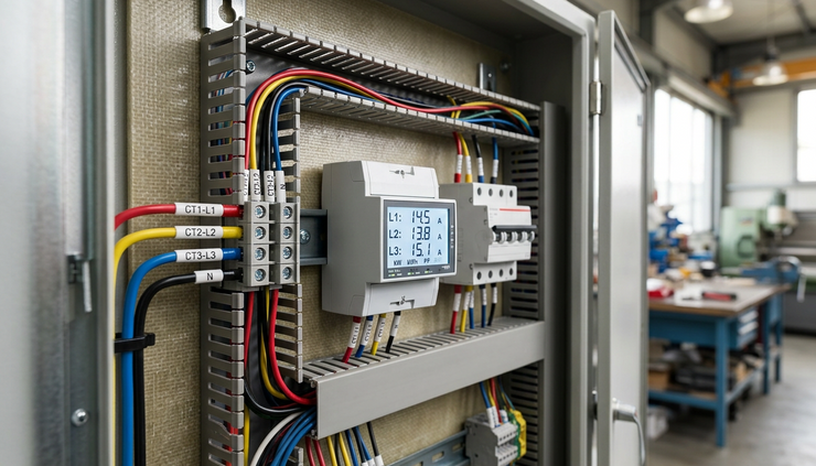
Phase mapping keeps voltage and current together
Three phase power measurement depends on pairing the correct current input with the correct voltage reference. The CT on L1 must be assigned to the L1 current input. The CT on L2 must match L2. The same applies to L3.
When phase mapping is wrong, current may still display on all three phases. That can hide the fault. The giveaway is often in power factor, kW, or phase power values.
For example, if the L1 CT is connected to the meter’s L2 current input, the meter may combine L1 current with L2 voltage. The current number can look reasonable, but the calculated real power for that phase will be wrong. In some cases, one phase may show negative kW while the total looks lower than expected.
The phase allocation should be checked in two ways:
Trace the physical wiring
Confirm which conductor passes through each CT. Then confirm where each CT secondary lands on the meter.
Compare live readings
With the system running, check whether each phase voltage, current, kW, and power factor behaves as expected. A balanced motor load should not show one phase with a wildly different power factor unless there is a real electrical reason.
Colour coding can help, but it should not be trusted alone. Panels get modified. Conductors get sleeved. CT cables get extended. A label made during installation is useful only if it matches the final wiring.
CT polarity decides whether power flows the right way
CTs usually have markings that show orientation. Depending on the CT, these may appear as `P1` and `P2`, `K` and `L`, or arrows that indicate conventional current direction. The exact marking should be checked on the CT body and datasheet.
For a normal import load, the CT should face the correct direction from supply to load as required by the meter wiring diagram. If the CT polarity is reversed, the current magnitude may still look correct, but real power can show as negative. Energy may also accumulate in the wrong import or export register if the meter separates them.
Reversed CT polarity is especially easy to miss on sites with solar PV, battery systems, standby generation, or bidirectional feeders. A negative kW value may be correct during export. It may also be the sign of a reversed CT. The commissioning note should say what operating condition was present at the time of the check.
A quick polarity clue is this: for a known import-only load, watts should normally be positive on the importing phases. If one phase is negative while the others are positive, inspect that CT direction and its secondary wiring.

Reading checks prove the installation before handover
Commissioning is not complete when the meter powers up. It is complete when readings make electrical sense.
A practical reading check starts with voltage. Confirm that the displayed voltage matches the supply type. On a three phase four wire system, line-to-neutral and line-to-line values should be reasonable for the site. On a three wire system, check that the meter is configured for the correct wiring method.
Next, check current. Compare the meter current readings with a suitable clamp meter or another trusted reference. The values do not need to match perfectly in every case, especially on fluctuating loads, but they should be close enough to confirm the CT ratio and phase allocation.
Then check real power. If a known load is available, use it. A heater bank, motor, pump, compressor, or lighting load can provide a useful reference. For a simple resistive load, kW should be close to voltage times current, adjusted for single or three phase calculation. For motors and drives, power factor will change the relationship, so do not expect kVA and kW to be the same.
A suitable commissioning check usually includes:
Voltage on each phase
Current on each phase
Phase power in kW
Total power in kW
Power factor by phase and total
Frequency
Import and export direction where relevant
Energy accumulation over a short test period
Communications data compared with the front display if a monitoring system is connected
The last point matters. A meter can display correct values locally while the supervisory system scales them again in software. If the meter sends a value that already includes the CT ratio, the receiving system should not apply the CT multiplier a second time.
Common symptoms point to specific commissioning faults
Meter faults do happen, but many odd readings come from configuration or wiring. A structured symptom check saves time.
Symptom | Likely cause | Check to make |
Current reads at a fixed fraction of expected value | Wrong CT ratio or multiplier | Compare configured ratio with CT nameplate |
Current reads correctly but kW is wrong | Phase mismatch between voltage and current | Trace CTs and voltage references phase by phase |
One phase shows negative kW on an import load | Reversed CT polarity or swapped secondary leads | Check CT direction and S1/S2 wiring |
Total kW is lower than expected | One or more phases mapped incorrectly | Check individual phase kW and power factor |
Power factor looks impossible or unstable | Phase allocation error, low load, or distorted load | Confirm wiring before assuming load behaviour |
Energy does not accumulate as expected | Import/export setting, pulse scaling, or communications scaling error | Compare display registers with remote readings |
All readings are zero current | CT circuit open, wrong input type, or unloaded circuit | Verify CT secondary continuity and load state |
This table is not a replacement for the manual or safe electrical testing. It gives a starting point. The meter model, wiring diagram, CT type, and site conditions still control the correct procedure.
A good commissioning record prevents repeat faults
A written commissioning record is a simple way to protect the quality of the data. It also helps anyone who returns to the site later.
The record should include:
Meter model and serial reference
Wiring mode selected in the meter
CT ratio and secondary rating
CT type and accuracy class where known
Phase allocation for voltage and current inputs
CT orientation notes
Displayed voltage, current, kW, and power factor values at test time
Reference instrument readings where used
Any software scaling applied outside the meter
Date, load condition, and person responsible for the check
This information becomes valuable when loads change, monitoring software is added, or a panel is modified. Without it, a later technician may see an odd trend and have to re-prove the installation from scratch.

Select the meter and CT package before the panel is built
The easiest commissioning job starts before installation. If the meter, CTs, and monitoring requirement are selected together, there is less chance of mismatched inputs, awkward CT fit, or poor low-load resolution.
When specifying an Acrel meter and CT package, gather these details early:
Supply type and nominal voltage
Number of phases and neutral arrangement
Maximum and normal load current
Conductor or busbar size
Panel space and access for CT installation
Need for split-core or solid-core CTs
Required readings, such as amps, kW, kWh, power factor, harmonics, or demand
Communications requirement, such as Modbus or pulse output
Accuracy expectations
Any generation, battery, or bidirectional power flow
ProSense Instruments can help match these requirements to a suitable Acrel meter and current transformer set. That support is useful for new panels, retrofit monitoring, sub-metering projects, and energy data upgrades where the readings need to be trusted from day one.
The final test of any metering job is simple. The numbers should agree with the installation. Correct CT ratios give the meter the right scale. Correct phase mapping gives the meter the right electrical reference. Sensible reading checks prove that the configuration, wiring, and displayed data all point in the same direction.


Comments