
Why Gas Flow Meters Fail in Heat Moisture and Dust
Updated: 2 days ago
A gas flow meter can look perfectly healthy on a data sheet and still fail in the field. In Australia, the usual causes are not mysterious. They are heat, moisture, and dust.
Those three conditions change how the meter senses flow, how the transmitter handles signals, and how long the installation stays stable between calibrations. The problem is that failure is not always obvious. A meter may still display a number, trend in the control system, and pass a quick visual check while reading 2% or 5% away from reality.
That small error can become expensive fast. At a boiler, poor natural gas measurement can lead to fuel overconsumption. In custody transfer, even a small percentage error can turn into serious money over a year. The meter is not just an instrument. It is part of the financial and energy balance of the site.
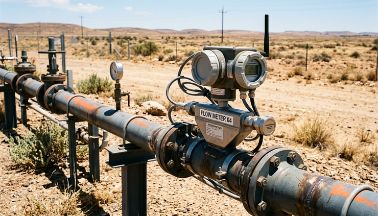
Field conditions beat laboratory conditions
Most flow meters are calibrated under controlled conditions. That is useful, but it does not guarantee field performance.
A meter calibrated at 25°C in a clean workshop may behave differently when it sits in direct Queensland sunlight, next to hot pipework, inside a cabinet with poor airflow, or near a dusty haul road. The instrument still has the same stated accuracy, but the installation has changed the operating reality.
The most common gap is between rated conditions and actual installed conditions. A meter might be rated for a temperature range, but that rating may apply to the process connection, the sensor body, the electronics, or a specific version of the transmitter. Those details matter.
A good specification should account for:
Ambient temperature at the transmitter
Process gas temperature
Radiant heat from sun and nearby equipment
Humidity and condensation risk
Dust loading and particle size
Pipe vibration
Pressure and temperature compensation
Access for inspection and maintenance
If those conditions are not checked before installation, the meter may spend its life outside the environment it was selected for.
Heat makes transmitter electronics drift
Heat damage is one of the biggest causes of gas flow meter error in Australian installations.
When ambient temperatures regularly exceed 45°C, transmitter electronics can drift. In direct sun, the temperature inside a housing can climb well above the surrounding air temperature. Add radiant heat from pipework, a nearby furnace wall, or a compressor package, and the electronics may operate near their limits for long periods.
Meters calibrated at 25°C can show a different output once the transmitter sits in extreme heat. In field conditions, errors of 2% to 3% are realistic when the meter is exposed to high ambient temperature and direct sunlight.
The fix is not always a new meter. Often, the installation needs to change.
Common heat controls include:
Remote-mounted electronics Move the transmitter away from radiant heat while leaving the sensing element in the line.
Sun shields Reduce direct solar loading on outdoor transmitters.
Better cabinet ventilation Avoid trapping heat around electronics in sealed boxes.
Correct temperature rating Check the rating for the full assembly, not only the sensor body.
Cable and gland selection Use components suited to the same heat exposure as the instrument.
Heat-related problems often show up as slow drift rather than sudden failure. The meter may read slightly higher or lower each summer, then appear to recover in cooler months. That pattern is a strong clue.
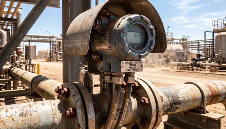
Moisture creates false signals and corrosion risk
Moisture causes a different kind of failure. It can attack the electronics, distort the sensor reading, or create erratic spikes that look like real process changes.
Coastal and humid areas, including places such as Gladstone, can expose instruments to high humidity and salt-laden air. If a transmitter housing breathes with daily temperature swings, moisture can condense inside. A housing can look sealed from the outside while still holding damp air.
Moisture is especially troublesome for thermal mass flow meters.
Thermal mass meters work by measuring heat transfer between a heated sensor and the flowing gas. If wet gas reaches the sensor, droplets or mist can change heat transfer for a moment. The transmitter sees that change and may report a flow spike or unstable reading.
Signs of moisture-related trouble include:
Erratic readings during weather changes
Spikes after rain or during humid mornings
Instability after shutdown and restart
Internal corrosion in terminals or housings
Water marks inside the enclosure
Intermittent signal faults
Wet gas can also create deposits on sensing elements. Over time, those deposits change response and reduce repeatability.
Moisture control starts with the basics. Use glands, seals, breathers, and housing ratings that suit the environment. Check conduit entries since they are common paths for water. Avoid mounting positions where water can pool around cable entries. For gas with entrained liquid, the meter type and upstream conditioning matter as much as the transmitter enclosure.
Dust and particulates change what the meter sees
Dust is a constant battle in mining regions. The Pilbara and Bowen Basin are harsh places for instrumentation, with fine dust, dry air, vibration, and heat all acting at once.
Dust affects meter types in different ways. It can coat exposed sensors, contaminate sample paths, clog filters, and interfere with moving parts. Even when particles do not break the meter, they can change the signal enough to reduce accuracy.
Thermal mass meters with exposed probes are vulnerable because dust can build up on the sensor. That coating changes heat transfer, which changes the flow reading. Filtration helps, but filters need maintenance. A forgotten filter can become a pressure drop problem or a hidden blockage.
Ultrasonic meters usually cope better with dusty gas because many designs are non-intrusive. They measure flow using sound paths through the gas rather than placing a sensing element directly in the stream. Dust can still cause problems if it fouls transducer faces or changes signal quality, but there are fewer parts exposed to direct wear.
Differential pressure devices can also suffer if impulse lines block. Orifice plates and similar primary elements may handle tough conditions, but the pressure taps and impulse tubing often become the weak points.
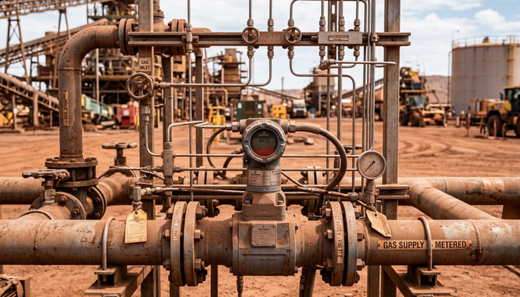
Gas flow measurement principles matter before meter choice
Before comparing meter brands, the measurement basis needs to be clear. Gases are compressible, so volume changes with pressure and temperature. That makes gas flow measurement more complex than liquid flow.
The first decision is whether the process needs mass flow or volumetric flow.
A volumetric meter reading 1000 m³/h at 20°C and 1 bar will not represent the same amount of gas if the temperature rises to 50°C at the same pressure. The volume changes because the gas density changes. The actual mass flow may not have changed at all.
Mass flow is often the better value when the goal is combustion control, emissions reporting, or energy use. Volumetric flow may be suitable when the process is already corrected to standard conditions, or when pressure and temperature compensation is handled elsewhere.
Measurement issue | Why it matters in gas service | What to check |
Mass versus volume | Gas volume changes with temperature and pressure | Decide whether the process needs kg/h, Nm³/h, Sm³/h, or actual m³/h |
Pressure compensation | Density changes as pressure changes | Confirm where pressure is measured and how the signal is used |
Temperature compensation | Hot gas occupies more volume | Check whether the meter measures, assumes, or receives gas temperature |
Gas composition | Density and heat capacity vary by gas mix | Confirm the meter is configured for the real gas, not a generic setting |
Turndown | Low flow can be harder to measure accurately | Match the meter range to normal and minimum flow, not only peak flow |
This is where many selection problems begin. The meter is asked to solve a measurement problem that was never clearly defined.
Different meter types fail in different ways
No meter type handles every condition perfectly. The best choice depends on gas quality, required accuracy, line size, pressure, turndown, maintenance access, and site exposure.
Meter type | Strengths | Common field problems |
Thermal mass | Direct mass flow, good for many clean gas applications | Sensitive to wet gas, coating, incorrect gas composition, and exposed sensor fouling |
Ultrasonic | Non-intrusive options, low pressure drop, good for larger lines | Needs good signal paths and suitable installation geometry |
Differential pressure | Familiar, tough primary elements, widely understood | Pressure taps and impulse lines can block, accuracy depends on installation and compensation |
Turbine | Good repeatability with clean dry gas | Moving parts wear, dust and liquids can damage internals |
Coriolis | Direct mass flow and high accuracy in suitable sizes | Higher pressure drop and cost, may not suit large gas lines |
Thermal mass meters are often selected because they are convenient and provide direct mass flow. They can be a good choice for clean, dry gas. In coastal humidity, wet gas, or dusty service, they need more care.
Ultrasonic meters are attractive where pressure drop matters and where intrusive sensors would suffer. They are often more tolerant of dirty conditions, but they still need proper straight runs, signal quality, and installation discipline.
Differential pressure systems can be reliable in harsh applications, yet the secondary elements need attention. A blocked impulse line can make a strong primary element useless.
The warning signs are easy to miss
A failing meter does not always alarm. Many failures appear as plausible numbers.
Look for patterns rather than single events. A reading that slowly drifts over weeks may be a heat problem. A reading that jumps during storms or humid mornings may point to moisture. A reading that becomes noisy after dusty shutdowns may suggest sensor coating or blocked lines.
Common warning signs include:
Fuel use rising without a matching production increase
Boiler control becoming harder to tune
Flow spikes during weather changes
Seasonal shifts in reported consumption
Differences between redundant meters
Repeated calibration adjustments in the same direction
Readings that look stable but do not match pressure, temperature, or production data
Cross-checks help. Compare gas flow against burner load, steam production, compressor performance, or inventory data. The goal is not to prove the meter wrong with one calculation. The goal is to spot patterns that deserve inspection.
A stable signal is not the same as an accurate signal. A meter can be consistently wrong.
Fix the installation before blaming the meter
Replacing the instrument often feels like the quickest answer. Sometimes it is necessary. But if heat, moisture, or dust caused the first failure, the replacement may fail the same way.
Start with the installation.
Check the transmitter location. If the electronics sit in direct sun, beside hot process equipment, or inside a sealed hot cabinet, move them or shield them. Remote electronics can be a simple and effective fix.
Inspect the housing. Look for moisture marks, corrosion, cracked seals, loose glands, and conduit that slopes toward the instrument. Small enclosure problems can create large measurement problems.
Review the gas condition. If the gas is wet, dirty, or variable in composition, confirm the selected meter type can handle it. Add filtration, separation, heat tracing, or conditioning only where it makes sense for the process. Every added component becomes something else to maintain.
Check the configuration. Confirm units, gas composition, reference conditions, pressure inputs, temperature inputs, and scaling to the control system. A good meter with the wrong configuration can look like a bad meter.
Set a maintenance interval based on actual conditions, not only the manual. A dusty mining site and a clean utility room should not have the same inspection plan.

The practical takeaway
Gas flow meter failures are rarely random. In Australian field conditions, heat, moisture, and dust explain many of the problems that appear as drift, spikes, unstable readings, or unexplained fuel use.
The best defence is not just buying a higher-spec meter. It is matching the measurement principle to the gas, then installing the instrument for the real environment. That means protecting electronics from heat, keeping moisture out of housings and sensors, managing particulates, and checking that compensation and configuration match the process.
If a meter reading affects fuel cost, production control, emissions, or custody transfer, treat small errors seriously. A few percent may not look dramatic on a screen, but over months of operation it can cost far more than the time needed to inspect the installation properly.
Need help with your application?
ProSense Instruments — explore instruments, sensors, data loggers and test equipment.
ProSense Solutions — discuss complete monitoring and automation systems.
ProSight Software — explore cloud dashboards, alarms and reporting. Device integration must be confirmed for your application.
Instrument enquiries: sales@prosenseinstruments.com.au | 1800 560 854
Project enquiries: sales@prosense.com.au. Software enquiries: info@prosightsoftware.com.

Comments