
8 Common Flow Meter Types and How They Work
Flow measurement looks simple from the outside. Fluid goes in, a number comes out. Inside the meter, though, the method can be very different depending on whether the goal is to measure clean water, steam, chemicals, fuel, slurry, or high-value process fluid.
The right meter depends on the fluid, pipe size, accuracy needs, pressure loss limits, installation space, and maintenance expectations. Some meters infer flow from pressure. Some count known volumes. Others use sound waves, magnetic fields, spinning rotors, or vibrating tubes.
This guide explains eight common flow meter types, how each one works, and where each tends to fit best.

A quick comparison of common flow meter types
Flow meter type | Basic measuring principle | Best fit |
Electromagnetic | Induced voltage from conductive fluid movement | Conductive liquids and slurries |
Differential pressure | Pressure drop across an obstruction | Water, gas, steam, and many process fluids |
Ultrasonic | Sound transit time or frequency shift | Large pipes, clamp-on measurement, clean liquids |
Positive displacement | Repeatedly traps and counts fixed volumes | Oils, fuels, viscous liquids, custody-style totalizing |
Coriolis | Tube twist caused by moving mass | Accurate mass flow and density measurement |
Turbine and paddle wheel | Rotor speed caused by fluid velocity | Clean, steady liquids and gases |
Vortex | Frequency of vortices shed behind a bluff body | Steam, gases, and clean liquids |
Rotameter | Float position in a tapered tube | Simple local indication for low to moderate flows |
1. Electromagnetic flow meters use induced voltage
Electromagnetic flow meters, often called mag meters, operate using Faraday’s law of electromagnetic induction.
A magnetic field is created across the pipe. When a conductive liquid flows through that field, it generates a voltage. The faster the liquid moves, the higher the induced voltage. Electrodes in the meter body detect that voltage, and the transmitter converts it into a flow rate.
The core relationship is simple: flow velocity is proportional to induced voltage. Once the meter knows velocity and pipe area, it calculates volumetric flow.
Mag meters have no internal moving parts. The bore is open, so they do not create an obstruction in the flow path. That gives them a major advantage in systems where pressure loss matters.
Common uses include:
Municipal water and wastewater
Chemical feed systems
Slurries and pulp
Process water
Food and beverage liquids, when materials are suitable
The main limitation is conductivity. A mag meter cannot measure nonconductive fluids such as most petroleum oils, deionized water in many cases, or gases. It also needs a full pipe to read correctly, since empty or partially filled pipe conditions can confuse the signal.
2. Differential pressure flow meters infer flow from a pressure drop
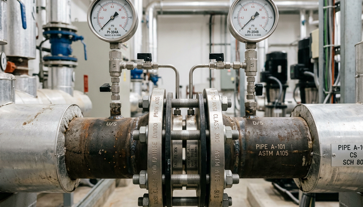
Differential pressure flow meters are among the oldest and most widely used flow measurement devices. They work by placing an obstruction in the pipe, such as an orifice plate, flow nozzle, or Venturi tube.
As fluid passes through the restriction, velocity increases and static pressure drops. Pressure taps before and after the restriction measure the difference. The meter then relates that pressure difference to flow rate using Bernoulli’s equation.
A key point is that flow does not rise in a straight line with differential pressure. In many DP applications, flow is proportional to the square root of the measured pressure difference.
Common primary elements include:
Orifice plates
Venturi tubes
Flow nozzles
Averaging pitot tubes
Wedge meters
DP meters can measure liquids, gases, and steam. They are common in plants because they are familiar, widely supported, and suitable for high-temperature and high-pressure service when designed correctly.
Their tradeoff is pressure loss, especially with orifice plates. They also need enough straight pipe upstream and downstream to give a stable velocity profile. In dirty, wet, or corrosive service, impulse lines and pressure taps may need regular attention.
3. Ultrasonic flow meters measure flow with sound
Ultrasonic flow meters use high-frequency sound pulses to measure velocity. They come in two main types: transit-time and Doppler.
Transit-time meters send ultrasonic signals both with and against the flow direction. Sound traveling with the flow arrives slightly sooner than sound traveling against it. The meter measures that time difference and calculates fluid velocity.
Doppler meters work differently. They send sound into the fluid and measure the frequency shift of echoes reflected from particles or bubbles moving with the flow.
Ultrasonic meters can be installed inline, but many are clamp-on devices. Clamp-on meters mount to the outside of a pipe, which means they do not require pipe cutting or process shutdown in many cases. That makes them useful for checks, temporary studies, and large pipe applications.
Transit-time meters generally work best with clean liquids. Doppler meters need suspended solids or bubbles to reflect the sound signal. Pipe material, wall thickness, liner condition, and installation quality all affect performance.
Ultrasonic meters are often chosen when:
The pipe is large
Low pressure loss is needed
A nonintrusive installation is preferred
Temporary flow verification is needed
The process fluid should not contact the sensor
4. Positive displacement meters count fixed volumes
Positive displacement flow meters measure flow by repeatedly capturing a known volume of fluid and counting how many times that volume passes through the meter.
Inside the meter, moving chambers, gears, pistons, rotors, or discs form precise pockets of fluid. Each movement represents a fixed volume. The total number of cycles gives total flow, and the cycle rate gives flow rate.
This direct counting method makes PD meters strong for totalizing applications. They are common for fuels, oils, hydraulic fluids, and other clean liquids, especially when the liquid has some viscosity.
Common positive displacement designs include:
Oval gear meters
Nutating disc meters
Rotary piston meters
Sliding vane meters
Helical gear meters
PD meters perform well at low flow rates and can maintain good accuracy over a useful range. They do not need long straight pipe runs in the same way many velocity-based meters do.
The moving parts are also the main tradeoff. Abrasive solids can wear internal components. Very dirty fluids may jam the mechanism. Pressure drop can rise as viscosity increases or as internal parts wear.
5. Coriolis meters measure mass flow directly
Coriolis mass flow meters use one or more vibrating tubes. An actuator vibrates the tube at a known pattern. As fluid moves through the vibrating tube, its inertia creates a twisting force known as Coriolis acceleration.
Sensors detect the twist or phase shift between points on the tube. That phase shift is proportional to mass flow rate. The meter can also measure fluid density by tracking changes in the tube’s vibration frequency.
This makes Coriolis meters different from most volumetric meters. They measure mass flow directly, not just velocity or volume. That is useful when the fluid density changes with temperature, pressure, or composition.
Coriolis meters are often used for:
Chemical dosing
Batch control
Custody and transfer applications where accuracy matters
Food and beverage processing
High-value liquids and gases, depending on design
Density monitoring
They offer high accuracy and strong diagnostic capability. They also have no rotating parts. Still, they can be more expensive than many other meter types, especially in larger pipe sizes. They may also need careful support to avoid vibration problems from nearby equipment.

6. Turbine and paddle wheel meters convert flow into rotation
Turbine and paddle wheel meters place a rotor in the flow stream. As fluid moves through the meter, it spins the blades. The faster the flow, the faster the rotor turns.
A pickup sensor detects blade movement and converts it into pulses. The meter electronics relate pulse frequency to fluid velocity. Once calibrated, the meter can report flow rate and total flow.
Turbine meters are often used with clean liquids and gases. Paddle wheel meters are common in water treatment, irrigation, pools, and light industrial systems.
Their advantages include fast response, simple output, and relatively low cost in many sizes. They work best when the flow is steady and the fluid is clean.
The limits are tied to the rotor. Bearings can wear. Debris can damage or slow the blades. Viscosity changes can affect calibration, especially in small meters. Like many velocity meters, they often need a proper straight run to reduce swirl and turbulence.
7. Vortex flow meters read the frequency of shed vortices
A vortex flow meter places a nonstreamlined object, called a bluff body, in the flow path. As fluid passes around it, swirling vortices shed alternately from each side. This repeating pattern is known as a vortex street.
The key idea is that the shedding frequency is proportional to flow velocity over the meter’s working range. A sensor detects the pressure pulses or vibrations caused by the vortices, and the electronics convert frequency into flow rate.
Vortex meters are popular for steam measurement, but they can also measure many gases and clean liquids. They have no moving rotor, which helps reduce mechanical wear.
They are often selected for:
Saturated and superheated steam
Compressed air
Natural gas in suitable applications
Process cooling water
Clean liquid utility lines
Vortex meters need enough flow velocity to create stable vortices. At very low flow rates, the signal can weaken. They also need attention to pipe vibration, since external vibration can interfere with detection if not handled well.
8. Rotameters use a float in a tapered tube
Rotameters, also called variable area flow meters, are simple, visual, and widely used for local indication.
A rotameter has a vertical tapered tube with a float inside. Flow enters from the bottom and pushes the float upward. As the float rises, the annular area around it increases. The float settles at the point where upward fluid force balances the float’s weight and drag.
The float height indicates flow rate on a marked scale. Higher flow lifts the float higher. Lower flow lets it drop.
A basic rotameter needs no external power. That makes it useful for quick local checks and simple systems. Glass tube models offer direct visual indication, while metal tube models suit tougher conditions and can include transmitters.
Common uses include:
Purge flows
Laboratory systems
Gas flow indication
Cooling water lines
Chemical feed monitoring
Rotameters must usually be mounted vertically with flow upward. They are also affected by fluid density and viscosity, so the scale must match the service fluid and operating conditions.

How to choose the right flow meter type
No single meter is best for every job. A good choice starts with the fluid and the reason for measuring it.
Ask these questions early:
Is the fluid a liquid, gas, steam, or slurry?
Is it clean, dirty, abrasive, corrosive, or viscous?
Does the meter need to measure volume or mass?
Can the process tolerate pressure loss?
Is the pipe always full?
What accuracy is needed?
Is local indication enough, or is a signal output required?
How much maintenance is acceptable?
For conductive wastewater, a mag meter may be a clear fit. For steam, DP or vortex measurement is often practical. For high-value chemical batching, Coriolis can be worth the cost. For a simple purge gas line, a rotameter may be all that is needed.
The best flow meter is the one that matches the actual service conditions, not just the pipe size or flow range on a datasheet.
The main takeaway
The eight common flow meter types use very different physics to answer the same question: how much fluid is moving through the pipe?
Mag meters use electromagnetic induction. DP meters use pressure drop. Ultrasonic meters use sound. Positive displacement meters count fixed volumes. Coriolis meters measure mass through tube twist. Turbine and paddle wheel meters use rotation. Vortex meters count shed vortices. Rotameters show flow through float position.
Understanding the working principle makes selection easier. It also helps explain why a meter that performs well in one application can fail in another. Match the meter to the fluid, the piping, and the purpose of the measurement, and the reading becomes far more reliable.


Comments