
What Is Instrumentation and Control in Industrial Plants
Updated: 2 days ago
A modern industrial plant can move thousands of gallons of liquid, heat materials to exact temperatures, compress gases, dose chemicals, and package finished products without constant manual adjustment. That does not happen by chance. It happens because the plant can measure what is going on, compare it with what should be happening, and adjust equipment in real time.
That is the work of instrumentation and control, often shortened to I&C.
Instrumentation and control is harder to describe than mechanical, electrical, or chemical engineering because it sits between many fields. It touches chemistry, mechanics, electricity, electronics, software, process behavior, hydraulics, pneumatics, and communication systems. In a refinery, paper mill, sugar plant, food facility, pharmaceutical plant, or chemical plant, I&C helps turn raw process conditions into safe, controlled, repeatable operation.

Instrumentation measures the process
Instrumentation is the part of I&C that deals with measurement. Industrial plants need to know what is happening inside pipes, tanks, reactors, furnaces, boilers, compressors, and packaging lines. Many of those conditions cannot be seen directly, so instruments act as the senses of the plant.
Common measured variables include:
Pressure
Temperature
Flow
Level
Density
pH
Conductivity
Weight
Speed
Position
Vibration
Gas concentration
A temperature sensor in a heat exchanger, for example, may detect whether a product is being heated enough. A pressure transmitter on a steam line may show whether adequate pressure is available for the process. A level transmitter on a storage tank may prevent overflow or protect a pump from running dry.
The word “instrument” can mean several things. It may refer to a simple local gauge, a field-mounted transmitter, an analyzer, a switch, or a complete measuring assembly. Some instruments only display a value. Others send a signal to a controller, alarm system, or control room.
In industrial work, the most useful instruments are usually those that produce a reliable signal. That signal lets the control system act without waiting for a person to read a dial.
Control keeps the process within limits
Control is the part of I&C that uses measurements to make decisions and take action. A control system tries to keep a process variable near a desired value called the setpoint.
A simple example is a tank level control loop.
A level transmitter measures the tank level.
The controller compares the measured level with the setpoint.
The controller sends an output signal to a control valve.
The valve opens or closes to change the flow into or out of the tank.
The level moves toward the setpoint.
This is called a feedback loop because the result of the action is measured and fed back to the controller.
The same idea applies across many industries. In a food plant, a steam control valve may hold a cooking temperature. In a pulp and paper mill, flow control may regulate chemical addition. In an oil and gas facility, pressure control may protect downstream equipment. In a pharmaceutical process, tight control may support product quality and repeatability.
A control system does not need to “understand” the whole plant in a human way. It needs good measurements, correct logic, properly sized final control elements, and well-tuned control behavior.
The main parts of an I&C system
Most instrumentation and control systems can be understood by looking at four basic parts.
Part | What it does | Example |
Sensor or primary element | Detects the process condition | Thermocouple, orifice plate, pH probe |
Transmitter | Converts the measurement into a usable signal | Pressure transmitter, level transmitter |
Controller | Compares the value with the setpoint and decides the action | PLC, DCS controller, standalone controller |
Final control element | Changes the process | Control valve, damper, variable frequency drive |
These parts may be close together or spread across a large plant. A flow element may sit in a pipe hundreds of feet from the control room. Its signal may travel through wiring or an industrial network to a controller. The controller may then send a signal to a valve positioner in the field.
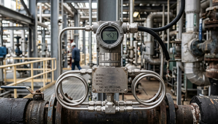
Sensors and primary elements
The sensor or primary element is the first point of contact with the process. It may touch the process directly, as with a temperature probe, or measure it indirectly, as with some flow and level devices.
Common examples include:
Thermocouples and resistance temperature detectors for temperature
Bourdon tubes, diaphragms, and strain gauges for pressure
Differential pressure elements, magnetic meters, Coriolis meters, and vortex meters for flow
Radar, ultrasonic, displacer, and differential pressure devices for level
Electrochemical probes for pH and conductivity
Each technology has strengths and limits. A magnetic flow meter works well for conductive liquids, but not for clean hydrocarbons or gases. Radar level measurement can work well in many tanks, but foam, agitation, and vessel geometry may affect performance. Selecting the right instrument requires knowledge of the process, the material, the installation, and the required accuracy.
Transmitters and signals
A transmitter takes the raw measurement and turns it into a signal that another device can use. In many plants, the traditional analog signal is 4 to 20 mA. In that range, 4 mA represents the lower end of the calibrated range, and 20 mA represents the upper end.
Digital communication is also common. Devices may use industrial protocols to send process values, diagnostic data, configuration settings, and status information. These systems help maintenance teams detect faults, check calibration data, and troubleshoot issues faster.
Signals can be:
Analog electrical signals
Digital network signals
Pneumatic signals
Discrete on-off signals
Older plants may still use pneumatic control systems, especially where compressed air was historically the standard. These systems often use air pressure signals to represent process values and controller outputs. Newer systems usually rely on electronic transmitters, digital controllers, and networked devices.
Controllers
The controller makes the decision. It receives a measured value, compares it with the setpoint, and calculates an output.
Many controllers use PID control. PID stands for proportional, integral, and derivative. These three actions affect how the controller responds to error.
Proportional action responds to the size of the error.
Integral action corrects error that remains over time.
Derivative action responds to the rate of change.
Not every loop uses all three actions. A simple pressure or flow loop may use proportional and integral action. Derivative action is used more carefully because noisy measurements can make it unstable.
Controllers may exist inside:
A distributed control system, or DCS
A programmable logic controller, or PLC
A small single-loop controller
A packaged equipment control panel
A microcontroller-based machine system
Large continuous process plants often use a DCS. Machines, skids, and discrete equipment often use PLCs. Many plants use both.
Final control elements
The final control element is the part that physically changes the process. The most common example is a control valve. A controller sends an output signal, and the valve changes position to increase or decrease flow.
Other final control elements include:
Dampers on air systems
Variable frequency drives on motors
Electric heaters
Solenoid valves
Pump speed controls
Louvers and vanes
Burner management outputs
The final control element must be sized and selected correctly. A poorly sized control valve can make even a well-designed controller behave badly. If the valve is too large, small movements may cause big process changes. If it is too small, it may not reach the required flow.
Open-loop and closed-loop control work differently
Not all control is the same. Two basic ideas help explain many plant systems: open-loop control and closed-loop control.
In open-loop control, the system takes action without measuring the result directly. For example, a pump may run for a fixed time to transfer liquid. The control action happens, but the system does not continuously check whether the target level has been reached.
In closed-loop control, the system measures the result and corrects itself. A level transmitter checks the actual tank level, and the controller changes the valve or pump speed until the level reaches the setpoint.
Closed-loop control is common in industrial plants because process conditions change. Feed composition may vary. Ambient temperature may shift. Equipment may foul. Operators may change production rates. Feedback control helps the plant adjust to these changes.
Open-loop control still has a place. It can be simple, fast, and useful where the result is predictable or where direct measurement is not needed. Many real systems combine both methods.
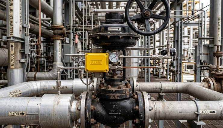
I&C connects the field with the control room
An industrial plant is spread across physical space. Instruments sit in hot, wet, noisy, dusty, or hazardous areas. Controllers may sit in cabinets. Operators may work from a control room interface. Maintenance teams use handheld communicators, laptops, test equipment, and calibration tools.
I&C brings these parts together.
A typical path may look like this:
A sensor detects pressure in a pipe.
A transmitter sends a signal through a cable.
An input module receives the signal in a control cabinet.
The controller processes the value.
The operator display shows the pressure.
The controller sends an output to a valve.
The valve positioner moves the valve.
The pressure changes, and the loop repeats.
Modern systems also log data. Trends help operators see whether a temperature is drifting, whether a pump is losing performance, or whether a control loop is cycling. Alarm systems warn the operator when values move outside safe or normal limits.
This connection between field devices, controllers, and operator displays is one reason I&C work requires such a broad knowledge base. A problem may come from the process, the wiring, the instrument, the controller configuration, the air supply, the communication network, or the final control element.
Safety and reliability are central to I&C
Instrumentation and control does more than keep production steady. It also supports plant safety.
Some instruments are used for control during normal operation. Others are used for alarms, trips, shutdowns, and protection. A high-high level switch on a vessel may shut down a feed pump. A flame scanner may confirm burner operation. A pressure switch may trip a compressor if discharge pressure rises too far.
Plants often separate basic process control from safety-related systems. The basic process control system handles routine operation. A safety instrumented system may handle critical shutdown functions when dangerous conditions occur.
Good I&C design considers:
The failure mode of instruments and valves
Alarm priority and operator response
Redundancy where needed
Proof testing and inspection
Calibration intervals
Power and air supply reliability
Electrical classification in hazardous areas
Clear drawings and documentation
A control loop that works well on paper can still fail in service if installation details are poor. Impulse lines can plug. Air lines can leak. Cables can be damaged. Valves can stick. Sensors can drift. That is why maintenance, testing, and records matter.
The interdisciplinary nature of I&C
I&C is interesting because it rarely belongs to one engineering box.
A single flow control problem can involve fluid mechanics, electrical signals, valve sizing, control tuning, piping layout, and software logic. A gas analyzer system may require chemistry, sample conditioning, heat tracing, tubing design, calibration gases, and alarm handling. A hydraulic press may involve pressure sensors, proportional valves, PLC programming, motion control, and machine safety.
This is why instrumentation and control engineers and technicians often develop a practical, systems-level mindset. They need to understand the process well enough to know what should happen. They also need to understand the devices well enough to know why it may not be happening.
The work may include:
Selecting instruments for new projects
Creating loop diagrams and instrument indexes
Designing control logic
Configuring PLC or DCS systems
Calibrating transmitters
Tuning control loops
Troubleshooting plant faults
Checking alarms and safety functions
Supporting commissioning and startup
Improving existing process control
In daily plant life, I&C teams often act as translators between process engineers, electrical teams, mechanical teams, operators, maintenance crews, and vendors.
A simple example from a heated tank
Imagine a tank that holds a liquid product that must stay at a fixed temperature. Steam flows through a heating coil inside the tank.
The I&C system may include:
A temperature sensor in the tank
A temperature transmitter
A temperature controller
A steam control valve
A local pressure gauge on the steam line
A high-temperature alarm
A low-level trip to protect the heating coil
During operation, the transmitter sends the tank temperature to the controller. If the temperature falls below the setpoint, the controller opens the steam valve. More steam enters the coil, and the product heats up. As the temperature rises, the controller reduces the valve opening.
If the level in the tank drops too low, a separate protection function may close the steam valve. This prevents overheating or damage. The operator display shows the temperature, valve position, alarm status, and trend.
This small example contains the main ideas found in much larger systems. The plant measures, compares, acts, displays, alarms, and protects.
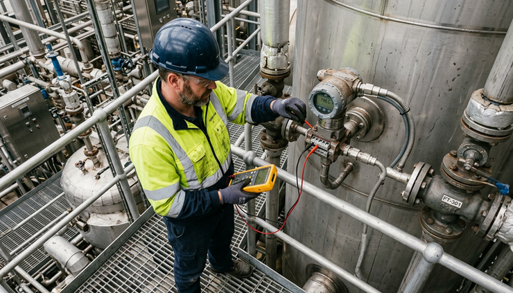
Why I&C matters in industrial plants
Without reliable instrumentation, operators would be partly blind. Without control, many processes would need constant manual adjustment. Without alarms and shutdown functions, abnormal conditions could grow into unsafe events.
Good I&C helps plants:
Keep products within specification
Reduce process variation
Protect equipment
Improve energy use
Support safe startup and shutdown
Detect abnormal conditions early
Record process history
Make operation more repeatable
The best systems are often quiet when they work well. Temperatures hold steady. Pressures stay within limits. Flows match production needs. Operators intervene less often. Maintenance teams can find faults before they cause larger problems.
Instrumentation and control is the discipline that gives an industrial plant its senses, its reflexes, and much of its operating intelligence. It combines engineering theory with field reality, which is why it is both demanding and rewarding. To understand a plant deeply, follow its measurements and control loops. They reveal how the process truly works.
Need help with your application?
ProSense Instruments — explore instruments, sensors, data loggers and test equipment.
ProSense Solutions — discuss complete monitoring and automation systems.
ProSight Software — explore cloud dashboards, alarms and reporting. Device integration must be confirmed for your application.
Instrument enquiries: sales@prosenseinstruments.com.au | 1800 560 854
Project enquiries: sales@prosense.com.au. Software enquiries: info@prosightsoftware.com.


Comments