
Understanding 4–20 mA Signals in Industrial Instrumentation
Updated: 2 days ago
A 4–20 mA signal looks simple, but a small wiring mistake can make a healthy transmitter read zero, overrange, or fail to communicate with a controller. The current loop is one of the most common ways to connect pressure, temperature, flow, and level instruments to a PLC, DCS, indicator, recorder, or alarm unit.
Its strength is also the reason it can be confusing. The same pair of wires may carry the signal and power the instrument. In other cases, the instrument has its own power supply and only sends a current signal. Some devices source current. Others merely accept it. Get that pairing wrong, and the loop will not work.
This guide explains how 4–20 mA loops work, how loop-powered transmitters differ from separately powered instruments, how active and passive interfaces match, and how to scale current into real engineering units.

Why industrial instruments use 4–20 mA signals
A 4–20 mA loop represents a process variable using current instead of voltage. At the low end of the calibrated range, the transmitter sends 4 mA. At the high end, it sends 20 mA.
For example, a pressure transmitter ranged from 0 to 100 psi will normally send:
Current | Meaning |
4 mA | 0 psi |
8 mA | 25 psi |
12 mA | 50 psi |
16 mA | 75 psi |
20 mA | 100 psi |
The signal span is 16 mA, because 20 mA minus 4 mA equals 16 mA. The 4 mA live zero is intentional. It lets the control system distinguish between a valid minimum reading and a dead loop.
If a 0 to 100 psi transmitter used 0 mA for 0 psi, then a broken wire could look like 0 psi. With a 4 mA live zero, a current near 0 mA usually points to a fault, open circuit, power loss, or incorrect wiring.
Current loops also handle long cable runs well. In a series loop, the same current flows through every device. Cable resistance creates voltage drop, but it does not change the current as long as the power supply has enough voltage to drive the loop.
That makes 4–20 mA practical in electrically noisy industrial areas, outdoors, and across long distances.
The basic parts of a current loop
A simple 4–20 mA loop has four elements:
A DC power source
A transmitter or current output device
A receiving input
The connecting cable and terminals
The transmitter measures the process variable and controls the current. The receiver measures that current, often by passing it through an internal resistor and reading the voltage across it.
Many analog input cards use a precision resistor, commonly 250 ohms. At 4 mA, the voltage across 250 ohms is:
`0.004 A × 250 Ω = 1 V`
At 20 mA:
`0.020 A × 250 Ω = 5 V`
That is why many systems describe a 4–20 mA signal as being equivalent to 1–5 V across a 250 ohm resistor.
The loop must be complete. Current leaves the supply, passes through the transmitter and input, then returns to the supply. If any terminal is open, reversed, or landed on the wrong common, the loop current cannot flow correctly.
Loop-powered transmitters and separately powered instruments are different
The first big distinction is how the field instrument gets power.
Loop-powered transmitters use the signal pair for power
A loop-powered transmitter is often called a 2-wire transmitter. The same two conductors provide operating power and carry the 4–20 mA signal.
A typical loop-powered pressure transmitter has two terminals:
Positive loop terminal
Negative loop terminal
The transmitter acts like a controlled current regulator. It takes power from the loop and adjusts the current to represent the measured value.
A basic loop path may look like this:
`+24 VDC supply → transmitter + → transmitter - → analog input + → analog input - → 0 VDC supply`
Some PLC input cards provide loop power internally. In that case, the card may have terminals labeled for transmitter positive and negative, and the external supply may not be separate. The principle is the same: the transmitter needs loop voltage, and the input must measure the resulting current.
Loop-powered transmitters are common because they reduce wiring and simplify installation. They suit many pressure, temperature, level, and flow applications.
Separately powered instruments use extra power terminals
A separately powered instrument has its own power connection. It may be called a 3-wire or 4-wire device, depending on how its signal and supply terminals are arranged.
Common examples include:
Magnetic flowmeters with AC or DC power
Ultrasonic level transmitters with separate supply terminals
Analyzers that need more power than a loop can provide
Smart instruments with displays, heaters, relays, or communications
In these devices, the 4–20 mA output may be isolated from the power supply, or it may share a common reference. The manual matters here. The output can be active or passive, and the receiving input must match it.
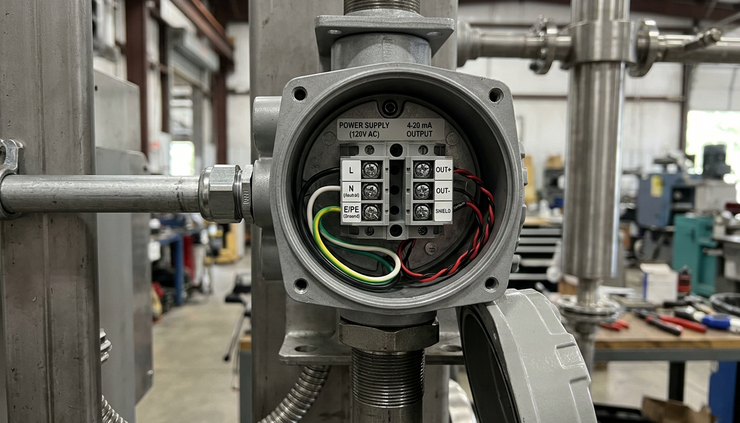
Active and passive interfaces must be matched
The words active and passive describe whether a device supplies loop power or only controls or receives current.
This is where many commissioning problems start.
An active output supplies current
An active current output sources the loop current itself. It has enough internal power to drive current through a passive receiving input.
A separately powered flowmeter, for example, may have an active 4–20 mA output. It sends current from its output terminal through the input resistor of the receiving device.
In that case, the PLC analog input should usually be configured as passive, or non-powered. It measures the incoming current but does not supply loop voltage.
A passive output needs an external supply
A passive current output does not supply loop power by itself. It behaves more like a controlled current path. It needs an external DC source in series.
Many 2-wire transmitters are passive from the control system point of view. They need the loop supply to operate.
Some 4-wire instruments also provide passive outputs. That can surprise technicians because the device already has power. The instrument is powered, but its analog output still needs an external loop supply.
A passive input only measures current
A passive analog input receives a current signal from an active output or from an externally powered loop. It does not provide excitation voltage.
A passive input works well with devices that source current. It will not power a 2-wire transmitter unless a separate supply is included in the loop.
An active input provides loop power
An active analog input supplies voltage for the loop. It is designed to connect directly to passive 2-wire transmitters.
If the input card provides 24 VDC loop power, the transmitter can be wired straight to the card. The card powers the transmitter and reads the current.
What happens when the match is wrong
Matching active and passive sides is simple once the rule is clear:
One side of the loop must provide power, and the other side must accept or regulate the current. Two active devices can fight each other. Two passive devices cannot make current flow.
Typical mismatch symptoms include:
The input reads 0 mA or near 0 mA
The signal is stuck at a fixed value
The transmitter powers up but the PLC reads nothing
A fuse blows or an input channel is damaged
The reading changes when a meter is inserted into the loop
When troubleshooting, identify which device is sourcing voltage before moving wires.
How to scale 4–20 mA into engineering units
A 4–20 mA input is only useful after the control system converts the current into meaningful units such as psi, °F, gallons per minute, or percent level.
For a linear transmitter, use this formula:
`Engineering value = LRV + ((mA - 4) ÷ 16) × (URV - LRV)`
Where:
LRV means lower range value
URV means upper range value
mA means measured loop current
The fraction `(mA - 4) ÷ 16` gives the signal as a percentage of span.
At 4 mA, the fraction is 0.
At 12 mA, the fraction is 0.5.
At 20 mA, the fraction is 1.
Worked example for pressure
A pressure transmitter is ranged 0 to 250 psi. The control system reads 14.4 mA.
Use the formula:
`Value = 0 + ((14.4 - 4) ÷ 16) × (250 - 0)`
`Value = (10.4 ÷ 16) × 250`
`Value = 0.65 × 250`
`Value = 162.5 psi`
So 14.4 mA equals 162.5 psi.
Worked example for temperature
A temperature transmitter is ranged -40 to 160 °F. The measured signal is 10 mA.
`Value = -40 + ((10 - 4) ÷ 16) × (160 - (-40))`
The span is 200 °F.
`Value = -40 + (6 ÷ 16) × 200`
`Value = -40 + 75`
`Value = 35 °F`
So 10 mA equals 35 °F.
Negative lower range values are common in temperature applications. The same formula still works.
Worked example for level
A tank level transmitter is ranged 0 to 15 ft. The current is 18 mA.
`Value = 0 + ((18 - 4) ÷ 16) × 15`
`Value = (14 ÷ 16) × 15`
`Value = 13.125 ft`
The tank level is about 13.1 ft.
If the control system displays percent instead, the same current is:
`(18 - 4) ÷ 16 × 100 = 87.5%`

Practical checks before blaming the transmitter
A bad reading does not always mean a bad instrument. Many 4–20 mA faults come from power, resistance, scaling, or wiring details.
Check the loop voltage requirement
Every transmitter needs a minimum voltage across its terminals to operate. This may be listed as a minimum supply voltage or as a load resistance chart in the datasheet.
The supply must cover:
The transmitter’s required operating voltage
The voltage drop across the analog input
The voltage drop across cable resistance
Any extra devices in series, such as indicators, isolators, or barriers
For a simple example, assume:
Supply is 24 VDC
Transmitter needs at least 12 V
Analog input is 250 ohms
Cable and terminals add 50 ohms
At 20 mA, the input and cable drop is:
`0.020 A × (250 Ω + 50 Ω) = 6 V`
That leaves:
`24 V - 6 V = 18 V`
The transmitter still has 18 V available, so the loop has enough voltage.
Now add a second 250 ohm device in series. Total resistance becomes 550 ohms.
`0.020 A × 550 Ω = 11 V`
That leaves 13 V for the transmitter. If the transmitter needs 12 V, the loop still works, but with little margin. If the supply sags or barriers add resistance, the signal may stop reaching 20 mA.
Check input resistance and burden
Analog inputs are not all the same. Some have a built-in current shunt. Others require an external resistor. Some accept current only on certain terminals.
If a 250 ohm resistor is used externally, place it where the receiver expects it. A resistor in the wrong location can create a voltage signal but not a valid loop current path.
Also check whether test tools add burden to the loop. A handheld meter in milliamp mode must be inserted in series. If connected across the loop like a voltage meter, it can short the signal or blow the meter fuse.
Check scaling in the control system
A loop can be electrically correct and still display the wrong value.
Common scaling mistakes include:
Scaling 0–20 mA instead of 4–20 mA
Entering the wrong engineering range
Reversing LRV and URV
Mixing units, such as bar and psi
Applying square root extraction twice for flow
Forgetting that a smart transmitter was re-ranged in the field
Square root extraction needs special care. Differential pressure flow transmitters may output either a linearized flow signal or a raw differential pressure signal. The control system should not apply square root extraction unless the transmitter output is set up for it.
Check polarity and commons
Most 4–20 mA loops are polarity sensitive. Reversed terminals may produce 0 mA, a fault current, or no transmitter display.
For multi-channel input cards, commons can also cause confusion. Some cards use isolated channels. Others group several inputs around a shared common. Wiring that works on one input module may not match another.
When in doubt, trace the loop as a series circuit from supply positive back to supply negative. Every device in the loop must be in the path.
Fault indication and out-of-range currents
A normal 4–20 mA process signal uses 4 mA to 20 mA. Readings outside that range often carry special meaning.
Many industrial systems follow conventions similar to NAMUR NE43, where transmitters use currents below the normal range or above it to flag a fault. A device might drive low, such as below about 3.6 mA, or drive high, such as above about 21 mA. Exact values depend on the transmitter and its configuration.
Do not assume every out-of-range value means the same thing. Check the instrument setup and the control system alarm limits.
Useful distinctions include:
Slightly below 4 mA may indicate under-range
Slightly above 20 mA may indicate over-range
Very low current may indicate open circuit or failed low alarm
Very high current may indicate failed high alarm or wiring fault
0 mA usually suggests an open loop, no power, blown fuse, or disconnected wire
A control system should treat these states differently. A tank at 0 percent level is not the same as a failed level transmitter. A temperature slightly above its calibrated range is not the same as a broken sensor.

A simple commissioning checklist
Before putting a loop into service, check the basics in a fixed order. It prevents guesswork.
Confirm the transmitter range and units.
Confirm whether the instrument output is active or passive.
Confirm whether the receiving input is active or passive.
Verify the DC supply voltage and polarity.
Calculate voltage drop at 20 mA.
Check the input resistance or external shunt resistor.
Measure loop current in series with a meter or loop calibrator.
Compare measured current with the displayed engineering value.
Test low, mid, and high values when possible.
10. Verify fault alarms and out-of-range behavior.
For a fast loop health check, force or simulate 4 mA, 12 mA, and 20 mA. The receiver should show 0 percent, 50 percent, and 100 percent of the configured range. If those three points are correct, the electrical input and scaling are likely correct.
The key idea behind every 4–20 mA loop
A 4–20 mA loop is a controlled current path. The transmitter represents the process by regulating current, and the receiver turns that current into a value. The loop only works when it has enough voltage, a complete series path, matched active and passive devices, and correct scaling.
When a reading looks wrong, avoid guessing. Identify the power source, follow the current path, calculate the expected value, and compare it with a real milliamp measurement. That method catches most faults quickly and keeps the focus on the loop, not just the transmitter.
Need help with your application?
ProSense Instruments — explore instruments, sensors, data loggers and test equipment.
ProSense Solutions — discuss complete monitoring and automation systems.
ProSight Software — explore cloud dashboards, alarms and reporting. Device integration must be confirmed for your application.
Instrument enquiries: sales@prosenseinstruments.com.au | 1800 560 854
Project enquiries: sales@prosense.com.au. Software enquiries: info@prosightsoftware.com.


Comments