
One Inverter or Separate Drives for Three Motors
Updated: 2 days ago
A single inverter can sometimes run three motors, but it is not a safe assumption. The right answer depends on how the motors operate, how they start and stop, what the inverter manufacturer allows, and how the existing control panel is wired.
If the three motors are two fans and a pump, the choice becomes even more important. Fans and pumps often have different duty cycles, different speed needs, and different fault conditions. One drive may work well when all three motors always run together. Separate drives usually make more sense when each motor needs its own control.
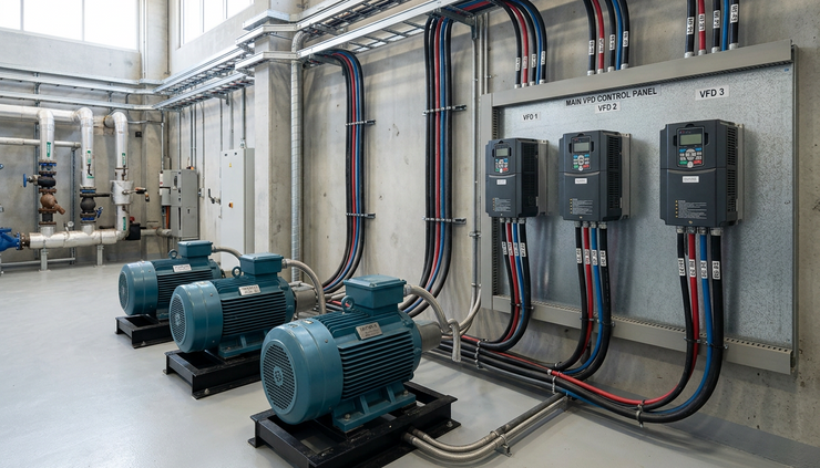
The short answer is yes, but only with conditions
One inverter may operate all three motors if all of the following points are true:
The inverter manufacturer permits multiple motors on one drive.
The combined motor current is within the inverter’s output rating.
Each motor has its own overload protection.
The motors are intended to start, stop, and change speed together.
The control system is designed for this arrangement.
The cable lengths, switching devices, and protection are suitable for inverter output.
That is the technical answer. The practical answer is a little different.
If the fans and pump need to start separately, stop separately, run at different speeds, or continue running when one motor has a fault, individual drives are usually the better choice. They cost more up front, but they give cleaner control and fewer compromises.
A motor inverter is not just a drop-in replacement for a contactor or a starter. It changes how power is delivered to the motor. It also changes how overload protection, emergency stops, interlocks, and fault signals should be handled.
What one inverter can and cannot do
A single inverter supplies one controlled output. If three motors are connected to that output, they receive the same voltage and frequency at the same time. That means they normally run at the same commanded speed percentage.
For some systems, that is fine.
Three identical extract fans serving the same area may all start together and ramp up together. A group of small circulation fans may not need independent speed control. In that kind of setup, one correctly sized drive can be practical.
For a mixed group, such as two fans and one pump, shared control can become awkward.
A pump may need to respond to pressure or flow. A fan may need to respond to temperature, air pressure, or a manual speed setting. If one shared inverter controls all three, the pump and fans must follow the same speed command. That may waste energy, reduce control accuracy, or create process problems.
There is also fault behavior to consider. If one motor trips its overload, what should happen to the other two? With one drive, the control arrangement may need to stop the whole group. With separate drives, one fan can stop while the pump continues, if the process allows it.
The manufacturer’s manual matters more than guesswork
Not every inverter is designed or approved for multiple-motor operation. Some drives can run several motors in a simple volts-per-hertz mode. Others are intended for one motor only, especially if they use sensorless vector control, motor identification routines, or advanced motor protection based on a single motor model.
The drive manual should state whether multi-motor use is allowed. It may also specify:
The recommended control mode.
Output cable limits.
Required output reactors or filters.
Motor protection requirements.
Restrictions on contactors fitted between the drive and motors.
How overloads should be selected.
If the manual does not clearly allow the arrangement, treat that as a warning. Ask the drive manufacturer or supplier before building the panel.
The question is not only whether the inverter can supply enough current. It is whether the whole circuit can protect every motor correctly under real operating conditions.
Current rating is only one part of sizing
The combined full-load current of the three motors must be within the inverter’s rated output current. That sounds simple, but the nameplate values deserve careful reading.
Do not size the inverter only from motor power in kilowatts or horsepower. Use the motor full-load current where possible. Motors of the same power can have different currents depending on voltage, efficiency, speed, and design.
For three motors on one drive, add the full-load currents together:
Motor | Full-load current | Included in total |
Fan 1 | From motor nameplate | Yes |
Fan 2 | From motor nameplate | Yes |
Pump | From motor nameplate | Yes |
Total | Sum of all three | Must be within drive rating |
The drive also needs enough capacity for the application. Fans and centrifugal pumps are often variable-torque loads, which are usually easier than heavy constant-torque loads. Still, acceleration time, starting load, and process conditions matter.
A pump starting against pressure may behave differently from a fan starting freely. If all three motors start at the same time, the drive must handle that combined acceleration load.
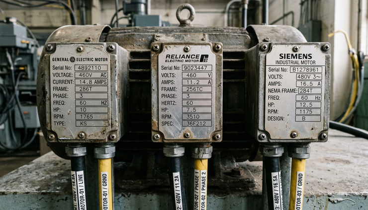
Each motor still needs individual overload protection
A common mistake is assuming the inverter’s overload function protects all motors equally. It usually does not.
When one inverter runs one motor, the drive can often provide motor overload protection because it measures the current going to that motor. When one inverter runs three motors, the drive sees only the total current.
That creates a problem.
If one motor is overloaded but the other two are lightly loaded, the total current may still look acceptable to the drive. The overloaded motor could overheat before the inverter trips.
For that reason, each motor needs its own overload protection. This is usually done with individual thermal overload relays, motor protection devices, or suitable electronic protection designed for use on inverter-fed circuits.
The protection must be compatible with the drive output. Standard devices do not always behave correctly with a variable frequency waveform. The selected protection should be suitable for the installation and should be set to match the motor nameplate current.
Starting separately changes the design
If the three motors always run together, one inverter is easier to justify. If they start separately, the case for separate drives becomes stronger.
Switching motors on and off at the output of a running inverter can be harmful unless the drive manufacturer permits it and the panel is designed for it. Opening or closing a contactor between the inverter and a motor while the drive is producing output can cause voltage spikes, overcurrent trips, contact damage, or drive faults.
Some systems use output contactors safely, but they need proper sequencing. The drive may need to stop output before a contactor changes state. Interlocks may be needed to prevent switching under load. The manual should be followed exactly.
Separate drives avoid much of this issue. Each motor has its own controlled output, so each motor can ramp, stop, fault, and restart independently.
For fans and pumps, that independence is often useful. One fan may run continuously, another may stage on when demand increases, and the pump may follow pressure. Trying to make that work through one shared inverter can lead to a panel full of compromises.
Existing control panels often need more than a small change
A motor inverter cannot be assumed to power the complete existing control panel unchanged. The old panel may have contactors, overloads, relays, timers, indicator lamps, a control transformer, an emergency stop circuit, and interlocks designed around direct-on-line or star-delta motor starting.
Adding an inverter changes the power path.
The drive output should normally go directly to the motor circuit, subject to any manufacturer-approved protection and switching. The input side of the drive is powered from the supply. Control commands are then wired to the inverter terminals or to a control system.
That means the existing contactors may no longer perform the same job. Some may be removed. Some may move to the drive input side. Some may remain as isolation devices only, depending on the design.
The control supply also needs review. A panel that once used contactor coils to control motors may now need run commands, speed references, fault feedback, reset signals, and safe stop wiring.
Emergency stop circuits need special care. An emergency stop should not rely only on a normal software stop command. Depending on the risk assessment and the drive model, the design may use safe torque off, input isolation, safety contactors, or another approved safety method.
This is where a qualified electrical designer should review the full circuit, not just the motor leads.

When one inverter is a good fit
One inverter can be a sensible choice when the motors behave like one combined load.
This often means:
The motors are similar in type and rating.
They always start and stop together.
They always run at the same speed.
The process can stop all motors together if one fails.
Individual overload protection is fitted.
The drive manufacturer supports the arrangement.
A good example would be a bank of identical fans serving the same function. If the control goal is simply to raise or lower airflow from all fans together, one drive may do the job well.
The advantages are clear. One inverter usually costs less than three. It takes less panel space. It needs fewer parameter settings. It may also simplify speed control if the motors truly act as one group.
The tradeoff is flexibility. You give up independent motor control. You also need to design the protection carefully, because the inverter is no longer protecting one known motor.
When separate drives are the better choice
Separate drives are usually better when each motor has its own job.
That includes systems where:
The pump and fans start at different times.
The motors need different speeds.
One motor may need to run while another is stopped.
Faults should be isolated to one motor.
Each motor has a different rating.
The process uses different sensors or control loops.
Energy saving depends on controlling each motor separately.
A pump controlled by pressure and fans controlled by air temperature are not really one load. They may share a panel, but they do not share the same control requirement.
With separate drives, each motor can have its own ramp time, maximum speed, minimum speed, overload setting, control input, and fault output. Maintenance also becomes easier. If one drive trips, the fault is linked to one motor circuit, not a group of three.
Separate drives can cost more, but they often save time during commissioning and troubleshooting. They also reduce the temptation to switch motors on the output of a running inverter.
The control strategy should come before the hardware choice
Before choosing one inverter or three, define how the system should operate.
Ask these questions first:
Do all three motors always run together?
Do they ever need to start or stop separately?
Do they need the same speed at all times?
What happens if one motor overloads?
What should the emergency stop do?
Are the existing contactors staying, moving, or being removed?
Does the inverter manufacturer allow multiple motors?
Are the overload devices suitable for inverter-fed motors?
Those answers will usually point to the right design.
If every answer supports group operation, one inverter may be acceptable. If the answers show independent operation, separate drives will be cleaner and safer.
Do not ignore cable length, EMC, and motor insulation
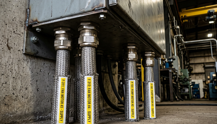
Drive outputs are not the same as a normal mains supply. Inverters create fast-switching voltage pulses. Long motor cables can increase stress on the drive and motor insulation. Multiple motor cables connected to one inverter can increase the total cable length seen by the drive.
The manufacturer may recommend output reactors, filters, screened cable, or limits on cable length. These details matter, especially in retrofits where motors and panels were not selected for inverter duty.
Older motors may also need attention. Some older insulation systems are less tolerant of inverter waveforms. Bearing currents can also be a concern on some installations. The risk depends on motor size, cable length, earthing, drive type, and site conditions.
This does not mean an inverter cannot be used. It means the motor and cable system should be checked as part of the design.
A practical rule of thumb
Use one inverter when the three motors can honestly be treated as one machine.
Use separate drives when the three motors need to behave like three machines.
That rule will not replace the manufacturer’s manual, a wiring diagram, or a proper safety review, but it helps avoid the most common mistake. The mistake is choosing one drive because it looks cheaper, then spending the savings on extra contactors, interlocks, fault workarounds, and commissioning time.
For a group of three identical fans, one drive may be a neat solution. For two fans and a pump with separate control needs, individual drives are usually the stronger design.
The safest next step is to gather the motor nameplate currents, the existing panel drawings, the required operating sequence, and the inverter manual. Once those are on the table, the choice becomes much clearer: one properly designed shared drive, or three separate drives that let each motor do its own job.
Need help with your application?
ProSense Instruments — explore instruments, sensors, data loggers and test equipment.
ProSense Solutions — discuss complete monitoring and automation systems.
ProSight Software — explore cloud dashboards, alarms and reporting. Device integration must be confirmed for your application.
Instrument enquiries: sales@prosenseinstruments.com.au | 1800 560 854
Project enquiries: sales@prosense.com.au. Software enquiries: info@prosightsoftware.com.


Comments