
Instrumentation and Control Basics for Industrial Plants
Updated: 6 days ago
A plant can only control what it can measure. That simple idea sits at the heart of instrumentation and control, often shortened to I&C.
In an industrial plant, raw materials move through pipes, tanks, reactors, furnaces, filters, compressors, conveyors, and packaging lines. Operators need to know what is happening inside that equipment, often under pressure, at high temperature, or in hazardous areas. They also need the process to respond, safely and repeatedly, when conditions change.
That is the job of instrumentation and control.
It blends chemistry, mechanics, electricity, electronics, software, communications, pneumatics, hydraulics, and process control. This mix makes the field hard to explain in one sentence, but easy to recognize once you see it in action. It is the temperature sensor on a reactor, the pressure transmitter on a steam line, the control valve feeding a distillation column, and the logic inside a PLC that starts a pump only when the conditions are safe.

What instrumentation and control means
Instrumentation is the part of engineering that deals with measuring process variables. These variables describe the state of a process.
Common process variables include:
Temperature
Pressure
Flow
Level
Density
pH
Conductivity
Vibration
Speed
Position
Weight
Gas concentration
A measurement instrument detects one of these physical or chemical conditions and turns it into useful information.
Control is the part that uses that information to make decisions and adjust the process. The adjustment may be simple, such as opening a valve when tank level drops. It may also be complex, such as balancing flow, temperature, pressure, and composition across an entire chemical unit.
Together, instrumentation and control give industrial plants the ability to run safely, consistently, and efficiently.
A helpful way to think about it is this:
Instrumentation tells the plant what is happening. Control tells the plant what to do about it.
Measurement is the starting point
Every control system begins with a measurement. If the measurement is wrong, the control action will also be wrong.
A measurement instrument usually has three basic jobs:
Sense the process condition
Convert that condition into a signal
Send the signal to a controller, display, recorder, or safety system
For example, a thermocouple senses temperature by producing a small voltage related to the temperature difference between two metal junctions. A pressure transmitter uses a sensing element that deflects under pressure, then converts that movement into an electrical signal. A magnetic flowmeter uses the movement of a conductive liquid through a magnetic field to calculate flow.
Different instruments use different physical principles, but the goal is the same. They translate real process conditions into data that humans and control systems can use.
Sensors, transmitters, and indicators
These terms are often used together, but they are not identical.
A sensor is the part that directly responds to the process condition. It may touch the process fluid, sit inside a thermowell, measure from outside a pipe, or detect motion from a machine casing.
A transmitter takes the sensor output and converts it into a standard signal. In many plants, this signal is a 4 to 20 mA analog current loop. Digital protocols are also common, including HART, Foundation Fieldbus, Profibus, Modbus, and industrial Ethernet systems.
An indicator displays the value locally or remotely. A pressure gauge on a pipe is a local indicator. A value shown on an operator screen in a control room is a remote indication.
Some devices combine these functions. A smart pressure transmitter, for example, contains the sensing element, electronics, signal output, diagnostics, and sometimes a local display.
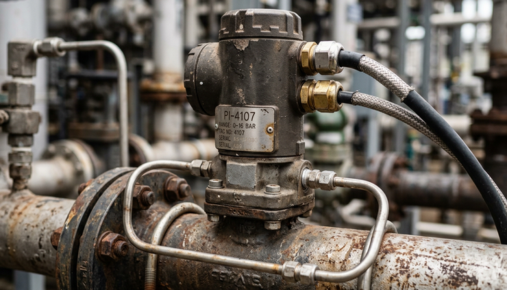
The main process variables in industrial plants
Industrial plants vary widely, but many of the same measurements appear again and again.
Temperature
Temperature affects reaction rates, product quality, energy use, and equipment safety. It is measured with devices such as thermocouples, resistance temperature detectors, infrared sensors, and filled-system thermometers.
In a food plant, temperature control may protect product quality. In a refinery, it may affect separation performance. In a pharmaceutical process, it may be part of a validated production step.
Pressure
Pressure measurements protect equipment and help control flow, boiling points, compression, and storage conditions. Pressure instruments may measure gauge pressure, absolute pressure, vacuum, or differential pressure.
Differential pressure is especially useful. It can indicate flow through an orifice plate, level in a pressurized tank, or filter blockage.
Flow
Flow measurement tells the plant how much liquid, gas, steam, or slurry is moving through a line. Flowmeters come in many forms, including differential pressure, magnetic, Coriolis, vortex, turbine, ultrasonic, and positive displacement meters.
The right choice depends on the fluid, pipe size, temperature, pressure, required accuracy, and whether the fluid is clean, dirty, corrosive, viscous, or aerated.
Level
Level measurement prevents tanks from overflowing or running dry. It also helps control inventory and process residence time.
Common level technologies include differential pressure, radar, ultrasonic, guided wave radar, displacers, floats, capacitance probes, and load cells. A simple sight glass may still be useful for local visual checking, even in advanced plants.
Analytical measurements
Analytical instruments measure composition or chemical properties. Examples include pH, conductivity, dissolved oxygen, moisture, turbidity, gas concentration, and chromatography.
These instruments often need more maintenance than pressure or temperature devices because they interact closely with the process. Dirty sensors, fouling, chemical coating, and sample conditioning problems can lead to poor readings.
How signals carry information
Once an instrument measures a variable, it must send the value somewhere.
The traditional 4 to 20 mA signal remains popular because it is simple, reliable, and easy to troubleshoot. In a typical setup, 4 mA represents the low end of the scale and 20 mA represents the high end. For example, a pressure transmitter ranged from 0 to 100 psi may output 4 mA at 0 psi and 20 mA at 100 psi.
Signals can also be pneumatic. Older plants, and some specialized systems, use 3 to 15 psi air signals for control. Pneumatic instruments are rugged and safe in some hazardous areas, but they need clean, dry instrument air.
Digital communication adds more data. Smart instruments can send the measured value, device status, diagnostics, configuration data, and alarms. This helps maintenance teams detect plugged impulse lines, sensor drift, valve problems, and electrical faults before they cause larger issues.
The basic control loop
The control loop is the core building block of industrial control.
A simple loop has four main parts:
Part | What it does | Example |
Measuring element | Reads the process condition | Temperature transmitter |
Controller | Compares the reading with the target | PID controller in a PLC or DCS |
Final control element | Changes the process | Control valve, variable speed drive, damper |
Process | Responds to the change | Heated tank, pump line, reactor |
Imagine a heated tank. The target temperature is 160°F. A temperature transmitter measures the tank temperature and sends the value to a controller. The controller compares the measured temperature to the setpoint. If the tank is too cold, it opens a steam control valve. If the tank is too hot, it closes the valve.
That is feedback control. The system measures the result, compares it with the desired value, then corrects the process.

Open-loop and closed-loop control
In open-loop control, the action does not depend on the measured outcome. A timer that runs a pump for five minutes is open loop. It may work, but it does not know whether the tank actually filled.
In closed-loop control, the controller uses measurement feedback. A level transmitter measures the tank level. The controller starts or stops the pump, or adjusts a valve, based on the actual level. Closed-loop control handles disturbances much better.
PID control
Many industrial loops use PID control. PID stands for proportional, integral, and derivative.
The proportional action responds to the current error. The integral action responds to accumulated error over time. The derivative action responds to how quickly the error is changing.
A well-tuned PID loop keeps the process near the setpoint without constant operator adjustment. A poorly tuned loop may oscillate, respond too slowly, or drive valves and equipment harder than needed.
PID tuning is both technical and practical. Engineers look at the process behavior, valve response, measurement speed, process dead time, and the risk of overshoot.
Controllers, PLCs, DCS, and SCADA
Control hardware depends on the size and type of plant.
A PLC, or programmable logic controller, is common in machines, utility systems, packaging lines, skids, and many discrete or batch processes. PLCs are strong at logic, sequencing, interlocks, and fast equipment control.
A DCS, or distributed control system, is common in large continuous-process plants such as refineries, chemical plants, pulp mills, and power generation. A DCS is designed for many control loops, operator graphics, alarms, trends, history, and plantwide process operation.
SCADA, or supervisory control and data acquisition, supervises equipment spread over large areas. It is common in pipelines, water systems, power distribution, and remote facilities. SCADA systems collect data, display status, send commands, and record events.
These systems often work together. A plant may use PLCs on packaged equipment, a DCS for process control, and SCADA for remote assets.
Final control elements make the process move
A controller cannot change a process by calculation alone. It needs a final control element.
Common final control elements include:
Control valves
On-off valves
Motor starters
Variable frequency drives
Dampers
Louvers
Heaters
Pumps
Compressors
Dosing systems
The control valve is one of the most common. It adjusts flow by changing the opening through which fluid passes. A valve may be driven by pneumatic pressure, electric power, or hydraulic force. A positioner helps the valve move to the requested position and stay there despite friction, pressure changes, or mechanical wear.
Variable frequency drives, often called VFDs, control motor speed. They are common on pumps, fans, blowers, and conveyors. Instead of throttling flow with a valve, a VFD can reduce the speed of the rotating equipment.
Safety and alarms are part of the system
Industrial control is not only about keeping a setpoint. It also helps protect people, equipment, product, and the environment.
Alarms warn operators when a process moves outside normal limits. A high-pressure alarm may give the operator time to reduce feed, open a vent, or shut down a pump. Alarm design matters because too many nuisance alarms can hide serious events.
Interlocks automate protective action. For example, a pump may be prevented from starting if the suction valve is closed or if the tank level is too low. A burner may shut down if flame detection fails.
Some plants also use a separate safety instrumented system, often called an SIS. It is designed to bring the process to a safe state when defined hazardous conditions occur. Safety systems are usually separated from normal control systems so one failure does not defeat both layers of protection.

Drawings and documents keep everything connected
Instrumentation and control work relies heavily on documentation. Without accurate documents, troubleshooting becomes slow and risky.
Common documents include:
Piping and instrumentation diagrams, known as P&IDs
Instrument indexes
Loop diagrams
Wiring diagrams
Cause and effect charts
Control narratives
I/O lists
Cable schedules
Datasheets
Calibration records
A P&ID shows process equipment, piping, valves, instruments, and control relationships. It is one of the most important drawings in a plant. Engineers and technicians use it to understand how a process is measured and controlled.
A loop diagram shows the full path of one instrument signal, from the field device to junction boxes, marshalling panels, I/O cards, controllers, and operator displays. It is essential for commissioning and troubleshooting.
Calibration and maintenance keep measurements trustworthy
Even good instruments drift, clog, wear, corrode, or fail. Calibration compares an instrument with a known reference and adjusts or records its accuracy.
Not every instrument needs the same calibration frequency. Critical safety, quality, or custody-transfer measurements need tighter control. Less critical indicators may be checked less often.
Maintenance teams also look for common problems such as:
Plugged impulse lines
Sensor coating
Loose wiring
Moisture in junction boxes
Failed power supplies
Air leaks on pneumatic systems
Sticking valves
Incorrect instrument ranges
Poor grounding or shielding
Good I&C maintenance is practical. It combines test equipment, process knowledge, drawings, and experience from the field.
Why I&C matters in real plants
Instrumentation and control turns industrial equipment into a manageable process. In oil and gas, it helps control pressure, flow, separation, and shutdown systems. In pulp and paper, it manages consistency, level, steam, and drying. In sugar processing, it supports evaporation, crystallization, and centrifuges. In pharmaceutical and food plants, it helps maintain repeatable conditions and traceable production.
The same principles apply across industries. Measure the process. Send a reliable signal. Compare the value with the target. Adjust the final control element. Protect the operation when conditions become unsafe.
That is the core of Instrumentation and Control Basics for Industrial Plants. The details can become advanced, but the foundation stays clear.
A good I&C system does not call attention to itself when everything is working. Temperatures hold steady. Tanks stay within limits. Pumps start only when they should. Operators see useful alarms instead of noise. Maintenance can trace faults with confidence.
The best next step is to look at a real process and identify the loop: the instrument, the controller, the final control element, and the process response. Once that pattern becomes familiar, the field of instrumentation and control becomes much easier to understand.
Need help with your application?
ProSense Instruments - explore instruments, sensors, data loggers and test equipment.
ProSense Solutions - discuss complete monitoring and automation systems.
ProSight Software - explore cloud dashboards, alarms and reporting. Device integration must be confirmed for your application.
Instrument enquiries: sales@prosenseinstruments.com.au | 1800 560 854
Project enquiries: sales@prosense.com.au. Software enquiries: info@prosightsoftware.com.


Comments