
How to Add Electrical Measurement to Existing BMS or SCADA Systems with Acrel via ProSense Instruments
Adding meters is the easy part. Getting useful electrical data into an existing BMS or SCADA screen, without bad values, slow updates, or weeks of driver work, takes better planning.
The buyer’s specification should do more than ask for “Modbus meters” or “power monitoring.” It should define the protocol, the exact measurements required, how the registers will be mapped, and how often the system needs fresh values. That is also the point where Acrel instrumentation, selected through ProSense Instruments, can be matched to the site rather than forced into it later.
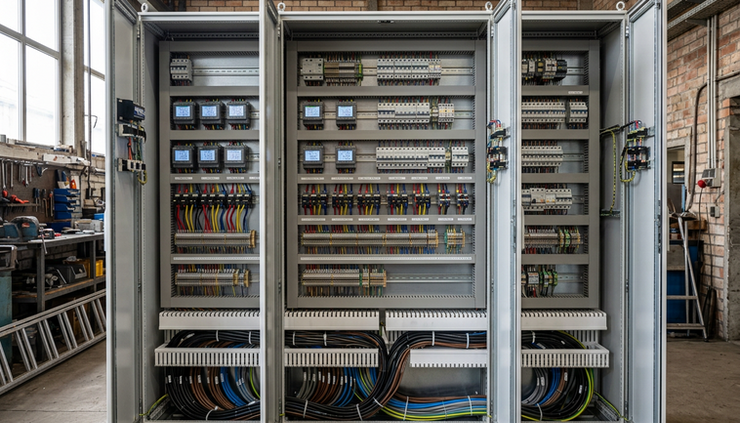
Electrical measurement projects usually sit between two worlds. On one side are switchboards, feeders, CTs, voltage references, and protection rules. On the other are BMS and SCADA platforms that expect clean points, known data types, and predictable polling. A clear specification connects those worlds.
Start with the system the meters must talk to
The first decision is not the meter model. It is the communication path.
Most BMS and SCADA systems already have preferred ways to collect field data. A modern SCADA system may poll devices over Ethernet. A BMS may use BACnet/IP, BACnet MS/TP, Modbus TCP, or Modbus RTU through RS-485. Older systems may have strict limits on point count, baud rate, or third-party drivers.
Before selecting Acrel meters, define the existing control environment:
The BMS or SCADA platform name and version
The protocols already enabled and licensed
The available ports, networks, and gateways
The distance between panels and controllers
The number of meters planned now and likely later
Any site rules for IP addressing, VLANs, or serial networks
The person or contractor responsible for integration
This information matters because two meters can measure the same electrical values but connect in very different ways. One may be a better fit for RS-485 multi-drop wiring. Another may suit Ethernet panels where each meter can sit on the building network. A third may need a gateway if the BMS expects BACnet while the field meters use Modbus.
ProSense Instruments can help narrow the Acrel range when these details are known early. That saves time because the selection can focus on meters, power quality devices, energy meters, or multi-circuit monitors that match the control system and the electrical job.
Specify the protocol clearly
A vague protocol line causes trouble. “Open protocol” is not enough. “Modbus compatible” is better, but still incomplete.
A useful specification names the protocol and the transport layer. For example:
Requirement | What to define |
Modbus RTU | RS-485 wiring, baud rate, parity, stop bits, device addressing, register range |
Modbus TCP | IP addressing method, port, unit ID use, network access rules |
BACnet MS/TP | Baud rate, MAC addressing, device instance range, point naming |
BACnet/IP | Device instance, network number, BBMD needs if routed across subnets |
Gateway-based connection | Field protocol on one side, BMS protocol on the other, point mapping ownership |
For many electrical monitoring systems, Modbus RTU remains common because it is simple, widely supported, and well suited to panels with multiple meters on a single RS-485 trunk. Modbus TCP is often cleaner where Ethernet is already available and the BMS or SCADA can poll IP devices directly.
BACnet may be preferred in building management projects because it fits common BMS workflows. If the chosen Acrel device model provides Modbus while the BMS contractor wants BACnet, the specification should include a gateway and clearly state who builds and validates the point map.
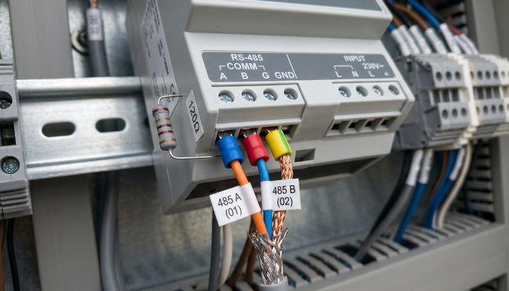
Do not leave these details until commissioning. Serial settings such as baud rate and parity look minor, but one mismatch can make a full meter network appear dead. IP settings can raise similar issues if site IT rules block traffic or require static addressing.
A good protocol specification also states the maximum number of devices per network segment. RS-485 networks need sensible limits, correct termination, and proper biasing. Long cable runs, mixed cable types, and star wiring can lead to intermittent readings that are hard to trace.
Define the measurements that actually matter
Electrical meters can report many values. The BMS or SCADA does not always need all of them.
A buyer should start with the operational purpose. The required measurements for tenant billing are not the same as those for load studies, alarm management, energy reporting, or power quality checks.
Common measurement groups include:
Voltage
Phase-to-phase and phase-to-neutral values, depending on the system.
Current
Per phase and neutral current where needed.
Power
kW, kVA, kVAr, power factor, and frequency.
Energy
Imported kWh, exported kWh where generation exists, and reactive energy if required.
Demand
Sliding or fixed interval demand values for load management and reporting.
Power quality
THD, harmonics, voltage imbalance, current imbalance, sags, swells, and events when supported by the selected device.
Status and alarms
Digital input status, relay output state, over-current alarms, phase loss, or communication fault flags.
Configuration values
CT ratio, PT or VT ratio, meter address, demand interval, and wiring mode.
Not every Acrel instrument will provide every group. That is why the point list should come before the final selector. A simple energy meter may suit a lighting panel. A main incomer feeding critical plant may need a multifunction meter with demand, alarms, and power quality values. A distribution board with many outgoing circuits may suit a multi-channel branch monitoring approach.
The best point list is specific. Instead of asking for “all meter data,” define the values the operator must see, trend, alarm, or report.
For example, a BMS energy dashboard might need:
Total imported kWh
Real-time kW
Power factor
Current per phase
Voltage per phase
Meter communication status
A SCADA load control screen might also need:
Demand kW
Breaker or contactor status
High current alarm
Low power factor alarm
Phase loss alarm
Relay output command feedback, if applicable
This keeps the integration work sensible. It also reduces unnecessary polling, which helps network performance.
Match Acrel instruments to the electrical application
Acrel instrumentation covers a wide range of electrical measurement tasks, so the selection should be based on the point list, installation constraints, and communication needs.
Typical selection questions include:
Is the measurement point single-phase or three-phase?
Is it low voltage direct measurement, or will PTs or VTs be used?
What CT ratio and CT type will the panel use?
Is the device for a main incomer, sub-main, final circuit, or machine?
Does the site need energy only, or full real-time power values?
Does the panel have space for a DIN-rail device or a door-mounted meter?
Is local display required?
Is RS-485, Ethernet, or another communication method preferred?
Are alarms, relay outputs, or digital inputs required?
Will the instrument support future expansion?
ProSense Instruments can support this selection process by checking the required measurements against available Acrel device types and communication options. That matters because a compatible meter is not just one that powers up and measures current. It must expose the right data in a format the BMS or SCADA can read reliably.
For retrofit work, physical details can be as important as protocol support. Panel space may be limited. CT installation may require shutdown planning. Existing CTs may have unknown ratios or burden limits. Door cut-outs may already exist. Network cabling may be blocked by fire compartments or distance limits.
A well-prepared buyer gives ProSense Instruments enough information to suggest practical hardware instead of a theoretical match.

Treat the register map as part of the deliverable
The register map is where many integrations slow down. A BMS contractor may have the protocol driver, but still needs to know exactly where each value sits and how to decode it.
For Modbus projects, specify that the supplier must provide the correct register map for the exact Acrel model and firmware where applicable. The map should include:
Register address
Function code
Parameter name
Units
Data type
Scaling factor
Signed or unsigned format
Word order for 32-bit values
Read-only or read-write status
Notes on resettable values or accumulated totals
The address base also needs attention. Some documentation uses one-based register notation, such as `40001`. Some software expects zero-based offsets, such as `0`. A mismatch of one register can turn voltage into nonsense or make every value appear shifted.
Use an integration table that the BMS or SCADA contractor can work from. The table below is only an example of the format, not a real Acrel register map.
Point name | Source document reference | Data type | Scaling | Units | BMS or SCADA tag |
Phase A voltage | To be confirmed from model register map | 32-bit integer | 0.1 | V | `MDB_PNL1_VA` |
Phase A current | To be confirmed from model register map | 32-bit integer | 0.001 | A | `MDB_PNL1_IA` |
Total active power | To be confirmed from model register map | 32-bit signed | 0.001 | kW | `MDB_PNL1_KW_TOT` |
Imported energy | To be confirmed from model register map | 32-bit integer | 0.01 | kWh | `MDB_PNL1_KWH_IMP` |
Power factor | To be confirmed from model register map | 16-bit signed | 0.001 | PF | `MDB_PNL1_PF` |
This table does three useful things. It gives the controls contractor the decoding rules. It gives the buyer a record of what was integrated. It also makes testing easier because everyone can compare the BMS value with the meter display or commissioning tool.
For BACnet projects, the same thinking applies. Instead of Modbus registers, define object type, object instance, object name, units, update behavior, and alarm limits if used.
Set update rates based on purpose, not habit
Faster polling feels better, but it is not always useful. It can overload serial networks, slow the BMS, and create noisy trend data. The update rate should match how the value will be used.
Real-time operator values usually need faster updates than energy totals. Alarms need prompt detection, but not every harmonic or accumulated counter needs to refresh every second.
A practical guide is:
Data type | Typical use | Sensible update approach |
Voltage and current | Operator display, abnormal load checks | Poll more often than energy totals |
kW and power factor | Load monitoring and control | Poll often enough to show real load changes |
kWh | Energy reporting | Poll less often because the value accumulates |
Demand | Capacity management | Match the demand interval and reporting need |
Power quality values | Diagnosis and trend review | Poll only the values needed, at a rate the device and network can support |
Alarm flags | Operator response | Poll often enough for the required response time |
On RS-485 networks, update rate depends on baud rate, number of devices, number of registers per device, and controller behavior. Polling 30 meters for dozens of values every second is very different from polling five meters for a short point list.
A clean specification should state:
Required screen refresh expectations
Trend logging interval
Alarm response expectation
Maximum acceptable communication delay
Number of values polled from each meter
Whether polling is grouped into blocks or individual points
Grouping matters. Modbus performs better when the BMS reads contiguous blocks of registers instead of many small scattered reads. When selecting Acrel instruments through ProSense Instruments, ask for register map guidance that helps create efficient read blocks where possible.
For many sites, a balanced approach works best. Fast-changing display values get a shorter interval. Energy and reporting values get a longer interval. Diagnostic values remain available but are not polled constantly unless needed.

Plan commissioning before the purchase order
A good purchase specification should include commissioning support expectations. This does not need to be complex, but it should remove guesswork.
At a minimum, the project should verify:
Meter wiring and phase rotation
CT polarity and ratio
Voltage reference and wiring mode
Meter communication settings
Device addresses or IP settings
Register decoding for key values
BMS or SCADA tag naming
Trend logging and alarm behavior
Readings against a known load or local display
Loss of communication alarm behavior
CT polarity deserves special attention. If CTs are reversed, power may show as negative or power factor may look wrong. If CT ratios are entered incorrectly, every current, power, and energy value will be scaled wrong. These are not software problems, but they often appear first on the BMS screen.
For safety, electrical installation and testing should be carried out by qualified personnel under the site’s isolation and electrical safety procedures.
Commissioning should also include a small set of acceptance tests. For example, compare meter display values to BMS values for voltage, current, kW, power factor, and kWh. Record any scaling factors and register choices. Save the final address schedule and point list with the project files.
What to send ProSense Instruments for a better Acrel selection
The fastest route to a compatible system is a simple pack of information. Before asking for a model recommendation, collect these details:
Existing BMS or SCADA platform and supported protocols
Preferred communication method, such as RS-485 or Ethernet
Number of metering points now and later
Single-line diagram or panel schedule
Circuit type and voltage level
CT ratios, CT type, and whether CTs already exist
Required measurement list
Any need for alarms, relays, or digital inputs
Panel space and mounting preference
Local display requirement
Register map or BACnet object expectations from the controls contractor
Required update rates for display, trend, and alarms
Site network or addressing rules
This gives ProSense Instruments the context to match Acrel instrumentation to the actual BMS or SCADA job. It also helps avoid under-specifying the device, overloading the network, or paying for measurement functions that will never be used.
The takeaway
Adding electrical measurement to an existing BMS or SCADA system works best when the buyer treats communication and data as part of the meter package.
Specify the protocol, physical connection, required values, register map details, and update rates before equipment is ordered. Share the existing system details with ProSense Instruments, then select Acrel instruments that match both the electrical installation and the integration path.
The result should be simple to test: the meter reads correctly, the BMS or SCADA displays the same values, trends update at the agreed interval, and alarms appear when they should. That is the difference between installing meters and delivering useful electrical measurement.


Comments