
Compressed Air Flow Measurement Buyer Guide for Pipe Size Range Pressure and Outputs
Compressed air is one of the most expensive utilities in a plant, and it is also one of the easiest to waste without noticing. A small leak, an oversized air blow-off, or a machine left running during idle time can add real cost month after month. A good flow meter turns that hidden use into numbers you can act on.
This buyer’s guide explains how to choose a meter for compressed-air flow measurement, with a focus on pipe size, flow range, pressure, temperature, standard versus actual flow, installation style, local display, and output signals such as 4–20 mA, RS485, and pulse.

Start with what the meter needs to prove
Before comparing product datasheets, define the job of the meter. A flow meter for a main compressor header has different priorities from one fitted to a single packaging machine.
Common goals include:
Measuring total compressed-air consumption for a site or building
Allocating air use by production line, department, or machine
Detecting leaks during shutdown periods
Tracking compressor demand for energy-management systems
Proving whether a machine uses more air than its specification
Triggering alarms when consumption rises above a normal range
Recording flow data for maintenance, quality, or sustainability reporting
The goal affects almost every buying decision. A meter used for cost allocation needs stable readings, useful totalization, and communications to a data system. A meter used on a machine may need fast response, a compact body, and a pulse or analog signal to a PLC.
Match the meter to the pipe size
Pipe size is the first hard limit. Flow meters are built for specific installation methods and pipe diameters. A meter that works well in a 2-inch branch line may be unsuitable for an 8-inch main header.
For compressed air, the main options are inline meters and insertion meters.
Inline meters fit into the pipe run
An inline meter has a body that becomes part of the piping. Air passes through the meter’s internal bore.
Inline meters are often a good fit for:
Smaller pipe sizes
Machine-level measurement
Skid-mounted equipment
New installations where the pipe can be cut easily
Applications where the meter supplier offers a calibrated body and sensor together
Inline meters can provide good accuracy because the internal flow path is controlled. The tradeoff is installation effort. The pipe must be cut, fittings must match, and downtime may be needed.
Insertion meters fit through a port in the pipe
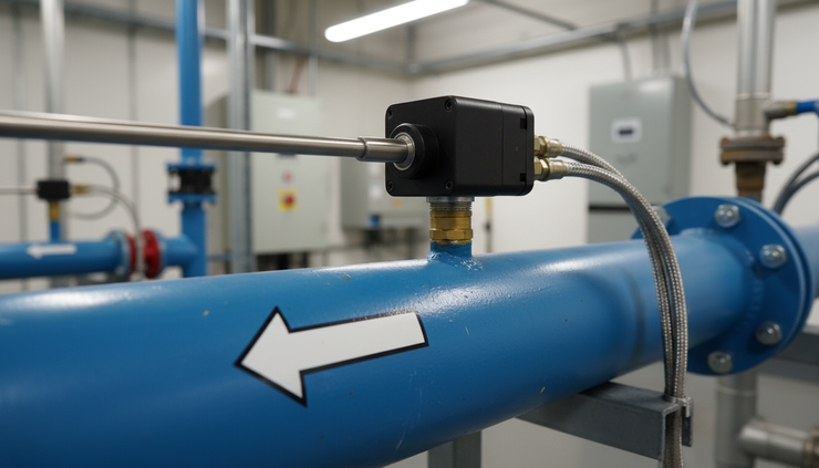
An insertion meter uses a probe inserted into the pipe through a fitting or valve. The probe measures velocity at a point in the air stream and converts that into flow using the pipe’s inside diameter.
Insertion meters are often a good fit for:
Larger pipe sizes
Main headers and plant distribution lines
Retrofit projects
Cases where cutting out a large pipe section is costly
Installations where hot-tap hardware is permitted
For insertion meters, the inside pipe diameter matters. Nominal pipe size is not enough, because wall thickness changes the internal area. A small error in diameter can create a real flow error.
If the meter asks for pipe diameter, use the true inside diameter based on pipe schedule, tubing size, or an actual measurement.
Choose the expected flow range, not just the maximum
A common mistake is buying a meter for the largest possible flow and ignoring the normal operating range. Flow meters have a usable range, often called turndown. If daily operation sits near the bottom of that range, the readings may be noisy or less useful.
Start by estimating three values:
Flow condition | Why it matters |
Minimum flow | Shows whether the meter can see leaks, idle use, or low production demand |
Normal flow | The range where the meter should perform best |
Peak flow | Confirms the meter will not overload during high demand |
For plant mains, the minimum flow may occur at night or during weekends. For a machine, the peak may occur during short cycles, such as blow-off, clamping, or pneumatic transfer.
If the process has short bursts, check the meter’s response time. A slow meter may smooth out the peaks. That can be fine for energy reporting, but not for machine diagnostics.
Flow units need attention
Compressed-air meters may display flow in units such as:
SCFM
Nm³/h
Nl/min
kg/h
ACFM
These are not interchangeable unless the reference conditions are known. SCFM and Nm³/h refer to standardized flow, while ACFM refers to actual flow at the flowing pressure and temperature.
For compressed-air consumption and energy tracking, standardized flow is usually more useful. It lets different lines and time periods be compared on the same basis.
Understand standard flow versus actual flow
This is one of the most important buying points.
Actual flow is the volume of air moving through the pipe at the actual line pressure and temperature. If the pressure changes, the same mass of air occupies a different volume.
Standard flow converts the measurement to a reference pressure and temperature. This makes the reading relate more closely to the amount of air consumed, not just the volume inside the pipe at that moment.
For example, a line at high pressure contains more air mass per cubic foot than a line near atmospheric pressure. If two meters report only actual cubic feet per minute, they may not tell the true consumption story unless pressure and temperature are included.
Many compressed-air thermal mass meters report standard flow directly because they sense mass flow and convert it to a standard volume. Other technologies may need pressure and temperature compensation to report standard flow correctly.
Before buying, confirm:
Which reference conditions the meter uses
Whether the display shows standard or actual units
Whether the output signal represents standard flow, actual flow, velocity, or total
Whether the reference can be changed to match your plant standard
Small unit mismatches cause confusion later, especially when values are shared with energy software or compared with compressor data.
Check pressure and temperature ratings
Compressed-air systems often run in a familiar pressure band, but the meter still needs proper ratings for the worst case. Do not size only for normal pressure. Look at the maximum line pressure, compressor discharge conditions, and any pressure tests the meter may experience.
Key checks include:
Maximum working pressure
Burst or proof rating if stated
Seal material compatibility
Temperature rating of the sensor and electronics
Whether the display can tolerate the local ambient temperature
Condensation risk in wet air systems
Most plant compressed-air lines are not extremely hot, but temperature can rise near compressor rooms, dryers, or outdoor piping. Electronics mounted on the pipe may see higher ambient heat than expected.
Also check air quality. Some meters handle clean, dry compressed air best. Oil carryover, liquid water, rust, or scale can affect the sensor or create maintenance issues. If the system is wet or dirty, install the meter after proper filtration and drying where possible.

Allow enough straight pipe
Flow meters need a stable flow profile. Elbows, valves, reducers, filters, dryers, and regulators can disturb the air stream. The result can be a reading that shifts even when actual demand is steady.
Most meters specify required straight pipe upstream and downstream. The exact length depends on meter type and nearby fittings. A simple bend may need less straight run than a control valve or regulator.
Good installation practice includes:
Put the meter away from elbows and partially open valves when possible
Follow the flow arrow on the body or probe
Install insertion probes at the correct depth and orientation
Avoid locations where liquid water can collect
Leave space for maintenance and display access
Make sure the pipe is full and pressurized during measurement
If the straight run is limited, ask the supplier how much error to expect. Some meters offer flow conditioners, but these add cost and pressure drop.
Decide between local display and remote data
A display is useful when technicians need to walk up to the line and see flow, total consumption, pressure, or temperature. For a single machine, a clear local display can help maintenance teams spot abnormal air use quickly.
A display may show:
Instant flow
Totalized consumption
Velocity
Pressure
Temperature
Alarm status
Error messages
Output scaling
For energy-management applications, the display is only part of the story. The meter should also send data to a PLC, building management system, compressor controller, data logger, or monitoring platform.
Choose the right outputs
Outputs determine how usable the meter will be after installation. Many buyers focus on the sensor and leave outputs until the end. That can lead to extra hardware, signal scaling problems, or missing totalizer data.
4–20 mA works well for live flow
A 4–20 mA output is a common analog signal for PLCs and control systems. It is usually scaled so 4 mA represents zero or minimum flow, and 20 mA represents the selected full-scale flow.
Use 4–20 mA when the control system needs:
Real-time flow trend
Alarm logic based on current flow
Compressor control input
Machine monitoring
Simple long-distance wiring with good noise resistance
Confirm whether the analog output represents standard flow, actual flow, pressure, or temperature. Some meters offer more than one analog output.
RS485 is better for richer data
RS485, often using Modbus RTU, can send multiple values over one communication link. That may include flow, total, temperature, pressure, unit status, and diagnostic data.
RS485 is a good choice when:
Several meters need to connect to one system
Totalized consumption must be read digitally
The plant wants fewer analog input cards
Data accuracy matters more than simple signal wiring
Meter settings need to be checked from a controller
Plan the network before installation. Addressing, baud rate, cable type, grounding, and termination all matter.
Pulse output is useful for total consumption
A pulse output sends pulses based on accumulated volume or mass. For example, one pulse may equal a selected amount of standard cubic feet or normal cubic meters.
Pulse output is often used for:
Consumption counters
Energy dashboards
Simple data loggers
Machine cycle air-use totals
Utility submetering
Check the pulse value, maximum pulse rate, and whether the receiving device can count fast enough during peak flow.

Match the meter to the application
Different jobs call for different priorities. The best meter for leak surveys is not always the best meter for a machine tool or compressor room.
Application | What to prioritize |
Plant air main | Wide flow range, insertion installation, totalizer, RS485, good low-flow sensitivity |
Department or line submetering | Standard flow units, pulse or RS485, clear total consumption data |
Individual machinery | Compact inline body, fast response, display, 4–20 mA or pulse output |
Compressor performance tracking | Stable flow data, pressure and temperature context, digital communications |
Leak monitoring | Low-end sensitivity, night and weekend trend data, totalizer accuracy |
Energy-management system | Standardized units, reliable outputs, clear scaling, integration support |
For compressed-air consumption projects, totalized flow is often the key value. Instant flow shows what is happening now, but total consumption shows what the plant paid to produce.
For machinery applications, compare air use across machine states. Track standby, idle, production, purge, and fault conditions. Many plants find that standby air use is higher than expected.
For energy-management applications, match air flow to compressor power, pressure setpoint, production volume, and time of day. This helps show whether savings came from leak repair, pressure reduction, equipment changes, or better shutdown practices.
Review accuracy claims carefully
Flow meter accuracy can be stated in different ways. A meter may quote accuracy as a percentage of reading, a percentage of full scale, or a combined statement. These are not the same.
A percentage of reading is usually more useful across a wide range. A percentage of full scale can create larger error at low flows.
Also check repeatability. For monitoring trends, repeatability can matter as much as absolute accuracy. If the meter repeats well, changes in consumption are easier to trust.
Ask these questions before purchase:
What gas is the meter calibrated for?
Is the calibration for compressed air or another gas?
What are the reference conditions for standard flow?
What is the minimum measurable flow?
How does accuracy change near the low end?
Is a calibration certificate supplied?
How often should the meter be recalibrated?
Can the meter be removed without shutting down the line?
Do not ignore pressure drop and maintenance
Inline meters can introduce pressure drop. In compressed-air systems, pressure drop can increase compressor workload or reduce performance at the point of use. Compare the expected pressure drop at normal and peak flow, not only the published maximum.
Insertion meters often create less pressure drop in large pipes, but they need correct positioning and may need periodic inspection.
Maintenance needs vary by technology and air quality. Thermal mass meters, differential pressure meters, vortex meters, and other types each have strengths. For many clean compressed-air systems, thermal mass meters are popular because they can report standard flow directly and perform well at low flow. Still, no technology is perfect for every line.
Build a simple selection checklist
Use this checklist before requesting a quote or approving a purchase:
Pipe nominal size and true inside diameter
Pipe material and schedule
Installation preference, inline or insertion
Minimum, normal, and peak flow
Required units, such as SCFM or Nm³/h
Standard or actual flow requirement
Maximum pressure and temperature
Air quality conditions
Available straight pipe
Display requirements
Output needs, including 4–20 mA, RS485, and pulse
Power supply available at the meter
Totalizer and data logging needs
Calibration and service expectations
A clear checklist prevents oversizing, missing signals, and unit mismatches.
The best meter is the one that fits the system
A compressed-air flow meter should make air use easier to understand, not harder. Start with the application, then confirm pipe size, flow range, pressure, temperature, units, installation style, and outputs.
For plant consumption and energy work, favor standard flow units, totalized data, and clean integration with RS485 or pulse output. For machinery, focus on the expected operating range, response time, local display, and the signal your PLC can use.
The right choice gives maintenance, production, and energy teams the same reliable picture: where the air goes, when it is used, and which changes reduce waste.


Comments