
Clamp-On Ultrasonic Flow Meters When Non-Invasive Measurement Works Best
Cutting into a live pipe is often expensive, slow, and risky. It may require shutdown permits, hot work controls, pressure isolation, draining, cleaning, welding, and leak testing. Clamp-on ultrasonic flow meters avoid that work by measuring flow from the outside of the pipe.
That advantage is real, but it has limits. A clamp-on meter can perform very well when the pipe, fluid, installation geometry, and application conditions support ultrasonic transmission. It can also produce unstable or biased readings when those conditions work against it.
The best results come from treating the meter as part of a measurement system, not as a universal sensor. Pipe material, wall thickness, liner condition, acoustic coupling, straight run, and liquid quality all affect the result.

How clamp-on ultrasonic measurement works
Most clamp-on ultrasonic flow meters use the transit-time principle. A pair of transducers sends ultrasonic pulses through the pipe wall and across the flowing liquid. One signal travels with the flow, and the other travels against it. The meter compares the travel times and calculates velocity from the difference.
That velocity then becomes volumetric flow when the meter knows the pipe inside diameter.
The basic calculation depends on several inputs:
Pipe outside diameter
Pipe wall thickness
Pipe material
Liner material and thickness, if present
Fluid type and approximate sound speed
Transducer spacing
Number of acoustic paths through the pipe
Some clamp-on meters also use Doppler measurement. Doppler meters rely on sound reflecting from suspended particles or bubbles in the liquid. They are useful for some dirty or aerated flows, but they are not ideal for clean liquids. Transit-time meters work best with clean, single-phase liquids, while Doppler meters need reflectors in the flow.
Many portable instruments can support both methods, but the application still decides which one will work.
When non-invasive measurement is effective
Clamp-on measurement works best when the ultrasonic signal can enter the pipe wall, pass through the liquid, and return to the receiving transducer with enough strength and clarity. The meter also needs a velocity profile that represents the actual flow in the pipe.
Good candidates often include:
Water distribution and process water lines
Chilled water, condenser water, and hot water systems
Glycol loops in HVAC and process cooling
Refined hydrocarbons in clean service
Chemical transfer lines with compatible pipe materials
Temporary flow surveys on existing systems
Verification of installed inline meters
In these cases, non-invasive measurement can reduce installation risk. It also allows technicians to move one portable meter across several locations during troubleshooting or commissioning.
Clamp-on meters are especially useful when the pipe cannot be opened. A facility may need flow data from a large cooling water main, but cutting in a spool piece could require a planned outage. A clamp-on unit can be installed from the outside and removed after the test.
They also help when contamination control matters. Food, pharmaceutical, and high-purity water systems often limit process intrusions. Since the transducers stay outside the pipe, the measuring device does not contact the liquid.
Non-invasive measurement can also support energy calculations. In a hydronic system, a flow meter paired with temperature sensors can help quantify heat transfer through a chiller, boiler, or heat exchanger. The flow reading still needs good installation conditions, but the method avoids adding pressure drop or new leak points.
Pipe material shapes the signal path
The pipe wall is not just a mounting surface. It is part of the ultrasonic path. Every material transmits and attenuates sound differently, and the meter must account for that behavior.
Common pipe materials such as carbon steel, stainless steel, copper, and many plastics can work well. Cast iron, cement-lined pipe, fiberglass-reinforced plastic, and heavily corroded steel can be more difficult. The issue is not simply strength or age. It is how consistently the material carries sound.
A sound wave passing through a clean steel wall behaves differently from one passing through a rough cast iron wall with internal tuberculation. The signal may scatter, weaken, or reflect in ways the meter cannot fully correct.
Pipe coatings and liners add another layer of complexity. Rubber, cement, epoxy, and plastic liners can change acoustic transmission and reduce signal strength. If the liner is thick or poorly bonded, the meter may struggle to distinguish useful signal from noise.
Practical checks before installing on a pipe
Before selecting a clamp-on meter or accepting a reading, confirm the pipe details as closely as possible.
Pipe factor | Why it matters | Field tip |
Material | Sets acoustic velocity and attenuation | Use actual pipe records when available, not visual guesses |
Outside diameter | Affects transducer spacing and flow area | Measure with a diameter tape or circumference tape |
Wall thickness | Determines inside diameter and acoustic path | Verify with ultrasonic thickness testing if records are uncertain |
Liner | Changes the signal path and inside diameter | Include liner material and thickness in the meter setup |
Surface condition | Affects coupling to the transducer | Remove loose paint, scale, rust, and insulation adhesive |
A small input error can create a meaningful flow error. Wall thickness is a common source. If the setup uses nominal pipe data but the pipe has heavy schedule wall, internal lining, or corrosion allowance, the inside diameter may be wrong. Since flow equals velocity multiplied by area, diameter errors affect the final flow value.
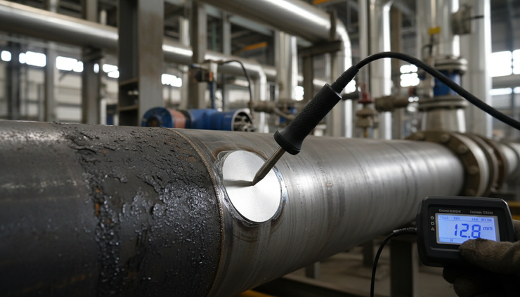
Wall thickness and pipe diameter affect accuracy
Clamp-on meters calculate flow from the velocity measured along the ultrasonic path and the pipe’s internal area. The instrument does not directly see the inside diameter. It depends on the setup data given by the user or selected from a pipe table.
That creates two main concerns.
The acoustic path must be modeled correctly.
The transducer spacing depends on how sound travels through the pipe wall and the liquid. A wrong wall thickness or material value can lead to weak signals, incorrect path geometry, or poor time measurement.
The internal flow area must be correct.
For round pipes, small diameter errors matter. If the inside diameter is overestimated, the calculated flow will be high. If it is underestimated, the flow will be low.
This matters most on larger pipes, old systems, and modified lines. A nominal 8-inch line may not have the same internal diameter when it is schedule 40 steel, cement-lined ductile iron, or plastic pipe with a thick wall. Even if the meter locks onto the signal, the calculated volume depends on the area value.
Good practice is to verify wall thickness when accuracy matters. Portable ultrasonic thickness gauges are widely used for this purpose. On insulated lines, the inspection team may need a small access window. On coated lines, they may need to prepare a clean measurement spot.
Straight run gives the meter a usable velocity profile
A clamp-on meter usually assumes that the measured acoustic path represents the average velocity in the pipe. That assumption works best when the flow profile is stable and predictable.
Elbows, tees, valves, pumps, reducers, strainers, and partially open control valves disturb the profile. They can create swirl, asymmetry, and turbulence. The meter may still display a steady reading, but the measured path may not represent the full cross-section.
Straight run helps the flow settle before it reaches the measurement point.
Manufacturers provide application-specific guidance, so their instructions should set the final installation requirements. As a general field rule, look for a location with several pipe diameters of straight pipe upstream and fewer downstream. More upstream straight run is useful after strong disturbances such as pumps, control valves, and out-of-plane elbows.
A good location often has:
Full pipe under all operating conditions
Stable pressure above vapor pressure
No nearby pump discharge if another location is available
No partially closed valve just upstream
Space to mount transducers at the required separation
Access for cleaning, coupling gel, straps, and cables
Vertical pipes can work well when flow travels upward because the pipe stays full. Horizontal pipes can work too, but transducer position matters. Mounting on the side of the pipe often avoids air collecting at the top and sediment settling at the bottom.
Example of straight run in a cooling water system
A facility needs to verify flow through a condenser water line. The most convenient pipe section sits two diameters downstream of a butterfly valve. The meter locks on, but the reading fluctuates as the valve position changes.
A better location exists 12 diameters downstream on the return header, away from the valve and pump discharge. The signal strength improves, and the reading tracks system changes more consistently. The second location is less convenient, but it gives a more reliable measurement.
That is a common tradeoff. The best measurement point is not always the most accessible one.

Liquid quality can decide whether the meter works
The fluid is the other half of the acoustic path. A clamp-on meter needs the ultrasonic signal to pass through the liquid in a predictable way.
For transit-time meters, the best liquid is clean, homogeneous, and single phase. Water, water-glycol mixtures, many oils, and compatible liquid chemicals often work well when pipe conditions also support the measurement.
Trouble starts when the liquid contains too much gas, too many solids, unstable mixtures, or changing properties.
Entrained air and gas weaken the signal
Air bubbles scatter and absorb ultrasonic energy. A small amount of entrained air may only reduce signal strength. A high gas fraction can make transit-time measurement unstable or impossible.
Common causes include:
Pump suction leaks
Poorly vented high points
Cavitation
Return lines discharging above liquid level
Chemical reactions that release gas
Low pressure near the liquid vapor pressure
If gas is present, move the measurement point to a higher pressure section, avoid pump suction, and choose a location where the pipe remains full. If the process naturally includes bubbles, a Doppler meter may work better than transit-time, if the application suits it.
Suspended solids can help or hurt
Suspended solids affect ultrasonic meters in different ways. Clean transit-time measurement does not need particles. Heavy solids can scatter signal and create noise, especially if solids concentration changes.
Doppler meters need suspended particles or bubbles to reflect sound. They can work on wastewater, slurry-like streams, and some dirty process liquids. Still, Doppler readings depend on reflector distribution. If solids settle, stratify, or vary widely, readings can shift.
For abrasive slurries, non-invasive measurement has a strong mechanical advantage because nothing protrudes into the flow. The challenge is acoustic reliability, not sensor wear.
Viscosity and temperature matter
Higher viscosity changes the flow profile, especially at low velocities. Temperature affects sound speed in the liquid and can affect pipe dimensions and coupling. Many meters compensate when given the right fluid and temperature inputs, but extreme or changing conditions deserve closer review.
A hot oil line, for example, may be measurable with the correct high-temperature transducers and couplant. A standard portable meter kit may not be suitable. The sensor rating, pipe surface temperature, and couplant limit all matter.
Selecting the right clamp-on flow meter
The right meter depends on the job. A short troubleshooting survey does not need the same instrument as a permanent energy monitoring installation.
Start with the measurement goal. Are you checking if flow exists, balancing a system, verifying pump performance, billing energy, or controlling a process? The required accuracy, logging functions, outputs, and installation effort change with the goal.
For selection, review these points before choosing a model:
Supported pipe materials and diameter range
Minimum and maximum wall thickness
Transit-time, Doppler, or dual-method capability
Temperature rating for transducers and couplant
Fluid compatibility and sound speed database
Required straight run and profile correction options
Data logging and diagnostic screens
Analog, pulse, or digital communications for fixed units
Ingress protection for outdoor or washdown locations
Hazardous area approvals when required
Diagnostics often matter as much as the flow number. A meter that displays signal strength, signal quality, gain, sound speed, and profile warnings gives the installer a better chance of catching poor conditions. Without diagnostics, a questionable installation can look more trustworthy than it is.
For permanent service, mechanical mounting also matters. Temporary chains and straps work for surveys, but long-term installations need stable hardware, weather protection, strain relief, and inspection access. Couplant selection is also critical. Some permanent installations use solid coupling pads or fixed mounting blocks to reduce maintenance.
Practical examples from the field
A few common scenarios show where the method fits.
Application | Likely result | Best practice |
Clean chilled water in steel pipe | Strong candidate | Use transit-time and verify pipe schedule |
Glycol loop on insulated pipe | Good candidate with preparation | Cut clean insulation windows and enter glycol concentration |
Old cast iron water main | Uncertain | Test signal strength before relying on data |
Aerated return line after a tank | Difficult for transit-time | Move upstream or review Doppler suitability |
Wastewater with suspended solids | Possible with Doppler | Confirm solids stay suspended across operating range |
Hot thermal oil | Possible with the right kit | Check transducer, cable, and couplant temperature ratings |
For a commissioning team, a portable clamp-on meter can confirm whether a pump is near its expected operating point without adding a temporary spool. For a maintenance team, it can compare flow before and after heat exchanger cleaning. For an energy team, a fixed clamp-on meter can support thermal energy monitoring where pipe entry is not practical.
None of these uses remove the need for good installation practice. They make that practice more valuable.

Tips for better readings during setup
Successful clamp-on measurement often comes down to careful field work. The following practices help reduce avoidable error.
Clean the pipe surface until the transducer sits flat.
Remove loose scale, thick paint ridges, insulation residue, and rust flakes.
Use the couplant recommended for the pipe temperature and installation duration.
Confirm the pipe is full before trusting the reading.
Avoid mounting at the top or bottom of a horizontal pipe when air or sediment may be present.
Enter actual wall thickness when accuracy matters.
Use the correct pipe material and liner settings.
Compare meter sound speed diagnostics with the expected liquid.
Check zero flow when the process allows it.
Record transducer spacing, signal quality, pipe data, and operating conditions with the result.
When readings look unstable, do not assume the meter is failing. Check for process causes first. Flow may be pulsating, a control valve may be hunting, air may be moving through the line, or the pipe may not be full.
When readings look stable but surprising, verify the setup data. A quiet display can still be wrong if the pipe diameter, wall thickness, or liner entry is wrong.
The best use case is the one the acoustics support
Clamp-on ultrasonic flow meters are powerful tools when the application supports them. They can measure flow without pressure loss, process contact, pipe cutting, or shutdown. That makes them valuable for surveys, verification, temporary diagnostics, and many permanent installations.
The strongest applications share the same traits: a clean acoustic path, known pipe dimensions, suitable pipe material, a full pipe, stable liquid quality, and enough straight run to form a usable velocity profile.
The weakest applications force the meter to guess through uncertain pipe construction, gas pockets, heavy solids, poor coupling, or disturbed flow. In those cases, a different measurement point, a different ultrasonic method, or an inline meter may be the better choice.
A clamp-on meter works best when it is selected and installed with the same discipline as any other flow instrument. Start with the pipe, confirm the liquid, respect the straight run, and use the meter diagnostics. The payoff is reliable flow data without opening the line.


Comments