
Choosing the Right Flow Meter for Compressed Air Thermal Mass vs Vortex and Pressure Compensation
Compressed air is one of the most expensive utilities in a plant, yet it is often measured with less care than water, steam, or natural gas. That makes flow meter selection more than an instrumentation detail. The wrong meter can hide leaks, distort demand data, and lead teams to size compressors or dryers based on guesswork.
A good compressed-air flow meter answers practical questions:
How much air does this line really use?
Is consumption rising over time?
Which production area wastes the most air?
Are compressors running because the process needs air, or because leaks and artificial demand are draining the system?
For most industrial compressed-air systems, the short list often comes down to thermal-mass flow meters and vortex flow meters. Both can work well, but they measure flow in different ways and perform best under different conditions. The best choice depends on pipe size, pressure range, air quality, flow profile, turndown, and whether the system needs pressure compensation.

Why compressed-air flow measurement is different
Compressed air looks simple because the fluid is just air. In practice, it is harder to measure than many liquids because air is compressible. Its volume changes with pressure and temperature.
A cubic foot of air at 100 psig contains far more mass than a cubic foot of air near atmospheric pressure. If a meter only reports volume in the pipe without accounting for conditions, the number may not reflect the amount of usable air being consumed.
That distinction drives many of the choices in flow meter selection.
Compressed-air measurement is used for several common tasks:
Main header monitoring
Tracking total demand from the compressor room.
Department submetering
Assigning air use to production lines, paint booths, packaging machines, or labs.
Leak detection
Watching overnight or nonproduction flow.
Equipment benchmarking
Comparing air use before and after maintenance or process changes.
Compressor control support
Understanding demand swings so control settings match plant behavior.
No single meter is best for every one of these jobs. Main headers tend to have large pipes, higher flow, and more stable velocity. Branch lines often see low flow, fast cycling, and greater variation. The meter technology should match those conditions.
Thermal-mass flow meters measure air by heat transfer
A thermal-mass flow meter measures how much heat moving air carries away from a heated sensor. The faster the mass of air moves past the sensor, the more heat it removes. The meter converts that heat transfer into mass flow.
This is why thermal meters are popular for compressed air. They are naturally suited to measuring mass flow, which can then be displayed as standard cubic feet per minute, often written as SCFM, or another standard flow unit.
Where thermal-mass meters work well
Thermal-mass meters are often a strong fit for:
Low to medium flow rates
Branch lines and submetering
Leak monitoring
Systems that need high turndown
Clean, dry compressed air
Installations where standard flow is the desired output
A major advantage is sensitivity at low flow. If a plant wants to detect small but persistent leakage during off-hours, a thermal meter can often see flows that some other technologies may miss.
Thermal meters also have no moving parts, so maintenance is usually low when air quality is good. Many insertion-style models can be installed in larger pipes without cutting out a full pipe section, though proper installation still matters.
Limits of thermal-mass meters
Thermal meters depend on heat transfer, so contamination can hurt accuracy. Oil mist, water droplets, pipe scale, or heavy particulate can coat the sensing elements. Wet air is especially troublesome because liquid water changes heat transfer and can damage sensors over time.
Gas composition also matters. Most compressed-air meters are calibrated for air or nitrogen-like gas properties. If the gas is not ordinary compressed air, the meter must be selected and configured for that gas.
Thermal meters also need a stable flow profile. Elbows, valves, reducers, dryers, filters, and regulators can disturb the air stream. Without enough straight pipe or a flow conditioner, readings can become less reliable.
Vortex flow meters measure vortices shed by a bluff body
A vortex flow meter places a shaped obstruction, called a bluff body, in the flow stream. As air passes around it, vortices form alternately from each side. The frequency of those vortices rises as velocity increases. The meter measures that frequency and calculates volumetric flow.
Vortex meters are widely used because they are durable, stable, and suitable for many industrial gases, steam, and liquids. In compressed air, they are often considered for larger lines or applications with moderate to high velocity.

Where vortex meters work well
Vortex meters are often a good fit for:
Main distribution headers
Larger pipe sizes
Medium to high flow rates
Applications with stable flow
Higher-temperature or harsher service than typical dry plant air
Installations where a full-bore inline meter is acceptable
Vortex meters do not rely on a heated sensor, so they can be less sensitive to some forms of coating than thermal devices. They also have no moving parts, and many designs hold calibration well when installed correctly.
Limits of vortex meters
Vortex meters have a lower flow limit. Below a certain velocity, vortices are too weak or irregular to measure accurately. That makes them less suitable for very low flows, leak detection, or branch lines that cycle between idle and short bursts.
They also measure velocity-based volumetric flow at line conditions unless paired with pressure and temperature compensation. For compressed air, that can be a deciding factor. If plant pressure changes through the day, uncompensated actual flow readings can misrepresent true air consumption.
Vortex meters can also be affected by vibration, pulsation, and poor upstream piping. Reciprocating compressors, fast-acting valves, and pressure regulators can create noise in the signal if the installation is not planned carefully.
Thermal-mass and vortex meters compared
The right choice becomes clearer when the technologies are compared by application need rather than by general reputation.
Selection factor | Thermal-mass meter | Vortex meter |
Best measurement type | Mass flow, often displayed as standard flow | Volumetric flow unless compensated |
Low-flow sensitivity | Usually strong | Limited by minimum velocity |
Turndown | Often high | Moderate, depends on meter and pipe size |
Air cleanliness needs | Best with clean, dry air | More tolerant in some dirty services, but still needs proper air quality |
Pressure compensation | Often not required for standard mass flow output, depending on design | Usually required for accurate standard flow |
Typical uses | Leak monitoring, submetering, smaller lines | Main headers, larger lines, steady flow |
Installation style | Inline or insertion | Usually inline, some insertion designs exist |
Key risk | Sensor contamination or poor gas match | Low-flow cutoff and uncompensated density changes |
A simple way to think about it is this: thermal-mass meters are often better when low-flow accuracy and standard flow reporting matter most. Vortex meters are often better when the flow is steady, velocity is high enough, and the installation supports compensation.
That is not a universal rule. It is a starting point for narrowing the field.
Standard flow and actual flow are not the same number
Compressed-air flow creates confusion because meters may report different “cubic feet per minute” values.
Actual flow is the volume of air moving through the pipe at the pressure and temperature that exist at that point. It is commonly shown as ACFM, or actual cubic feet per minute.
Standard flow converts that air volume to a defined reference condition. It is commonly shown as SCFM, or standard cubic feet per minute. The reference condition depends on the standard used by the meter, plant, or industry. Common references define a standard pressure and temperature so readings can be compared consistently.
This matters because compressed air shrinks and expands with pressure.
For example, if two branch lines both show the same actual flow but one operates at a higher pressure, the higher-pressure line is moving more air mass. That means it consumes more compressor capacity even though the actual volumetric number looks the same.
Standard flow helps answer the question plant teams usually care about:
How much compressor output did this process consume, independent of the local pipe pressure?
Actual flow still has value. It helps with pipe velocity checks, pressure drop reviews, and equipment sizing at line conditions. But for energy tracking, cost allocation, and leak studies, standard flow is usually the more useful number.
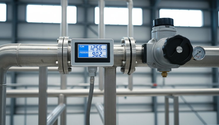
Pressure compensation keeps readings meaningful
Pressure compensation adjusts the flow calculation for changes in air density. In compressed-air systems, density changes mainly with pressure and temperature.
For many applications, pressure is the bigger variable. Plant headers may run at different pressures between shifts, during compressor sequencing, or when demand spikes. Branch lines may sit downstream of regulators where pressure varies with machine cycles.
If a meter does not account for pressure, two problems can appear.
The first problem is false stability. A line may appear to use the same actual flow even though pressure has changed and the mass of air consumed has changed with it.
The second problem is false savings. Reducing pressure can reduce artificial demand and leakage, which is often beneficial. But a meter that reports only actual volume may not show the real standard flow change accurately.
When pressure compensation is essential
Pressure compensation is especially useful when:
The meter is velocity-based, such as many vortex meters
The system pressure changes through normal operation
Readings are used for energy or cost tracking
Flow is compared across different pressure zones
The plant reports demand in SCFM
Air use is tied to compressor performance
A compensated vortex system often uses an integrated pressure sensor, a separate pressure transmitter, and sometimes a temperature input. The flow computer then converts actual line flow to standard flow.
Many thermal-mass meters internally infer mass flow from heat transfer and may display standard flow directly. Even so, the model, calibration basis, pressure limits, and correction approach should be checked. Do not assume every thermal meter handles every pressure range equally well.
How flow meters help find compressed-air waste
Compressed-air waste usually hides in plain sight. A hissing fitting may be obvious, but many losses are buried inside machines, drains, abandoned drops, open blowing operations, or controls that use air when no production is running.
Flow meters make waste visible by turning air use into a trend.
Track nonproduction baseline flow
One of the simplest tests is to record flow when production is off. If the plant is not making product but the compressor still supplies a steady demand, that baseline represents leakage, open uses, idle machines, or automatic drains.
A main header meter shows total off-shift demand. Submeters help locate which area carries that load.
Compare areas and shifts
Department meters can reveal patterns that pressure gauges cannot. One packaging line may use twice as much air as a similar line. A third shift may show high demand even with fewer machines running. Those differences point maintenance teams toward the right area.
Watch for step changes
A sudden increase in average flow often signals a new leak, a failed drain, a stuck valve, or a process change. Trend alarms can catch this before the extra compressor run time becomes normal.
Use flow with pressure data
Flow and pressure together tell a better story than either measurement alone. High flow with falling pressure may show a capacity or restriction issue. Rising flow with stable pressure may show new demand or leakage. Low flow with high pressure may point to artificial demand from overpressurized equipment.
Verify repair results
After fixing leaks or changing nozzles, the flow trend should confirm the result. This prevents a common problem where teams complete repairs but never prove that air demand actually dropped.

Practical tips for selecting the right meter
A good selection starts with the application, not the catalog page. Gather the real system conditions before choosing the technology.
Define the purpose of the measurement
Match the meter to the decision it will support.
For leak detection, prioritize low-flow sensitivity, trend logging, and stable standard flow output.
For main header monitoring, check maximum flow, pipe size, pressure rating, and communication options.
For allocation by department, focus on repeatability, ease of installation, and consistent reporting units across all meters.
For machine-level measurement, check response time and whether short air bursts need to be captured.
Know the flow range
Do not size a meter only for maximum compressor capacity. A meter that is too large may perform poorly at normal or low flow.
Estimate:
Minimum expected flow
Normal operating flow
Peak flow
Off-shift or idle flow
Future expansion demand
The minimum flow often decides whether vortex is suitable. If low-flow performance matters, thermal-mass may be the safer choice.
Confirm pressure and temperature conditions
Record normal and worst-case pressure at the planned meter location. Include regulator effects and pressure swings during machine cycles.
If standard flow reporting is needed from a velocity-based meter, include pressure compensation. If using a thermal meter, confirm its pressure range, calibration conditions, and output units.
Check air quality
Dry, filtered air supports both technologies. Wet or oil-laden air creates trouble.
Before installing a meter downstream of a compressor, think about dryers, filters, separators, and drains. A meter placed before adequate treatment may see water, oil, and debris.
For thermal meters, sensor fouling is a key concern. For vortex meters, liquid carryover and debris can still affect readings and long-term reliability.
Plan the piping installation
Most flow meters need straight pipe before and after the meter. Disturbed flow from elbows, tees, valves, reducers, and regulators can cause errors.
If straight run is limited, consider:
A different meter location
A flow conditioner
An insertion meter with careful depth and orientation
Manufacturer guidance for upstream and downstream piping
Never treat installation limits as minor details. A high-quality meter in a poor piping location can produce poor data.
Decide how the data will be used
A local display may be enough for spot checks, but waste detection needs trends. Consider outputs such as 4 to 20 mA, pulse, Modbus, BACnet, Ethernet, or connection to plant monitoring software.
Useful data features include:
Totalized flow
Average flow by shift
Minimum night flow
Peak demand
Alarm points
Pressure and temperature values
Exportable trend history
The best meter is the one that produces data people will actually use.
A simple selection guide
Use this quick guide to narrow the choice.
Application | Likely better starting point | Why |
Leak monitoring on a branch line | Thermal-mass | Strong low-flow sensitivity and direct standard flow reporting |
Main header with steady high flow | Vortex with compensation | Good fit for larger lines when velocity is high enough |
Department submetering | Thermal-mass | Useful turndown and simpler SCFM tracking |
Large pipe where insertion install is preferred | Thermal-mass insertion or insertion vortex | Selection depends on minimum velocity and accuracy needs |
Wet or dirty air service | Case-by-case review | Air treatment and sensor exposure may decide the design |
Cost allocation by area | Thermal-mass or compensated vortex | Consistent standard flow reporting matters most |
Compressor performance tracking | Compensated system | Flow, pressure, and trend data should align |
When in doubt, ask two questions.
Can the meter accurately measure the lowest flow that matters?
Will the meter report flow in the units needed for decisions, especially standard flow?
If either answer is no, keep looking.
The takeaway for compressed-air systems
Choosing a compressed-air flow meter is really a choice about trust. If the meter does not match the flow range, pressure conditions, air quality, and installation, the data will look precise but lead to poor decisions.
Thermal-mass meters often fit leak detection, submetering, and low-flow applications because they measure mass flow and commonly report standard flow directly. Vortex meters often fit larger, steadier flows, especially when paired with pressure and temperature compensation.
For energy tracking and waste reduction, pay close attention to the difference between actual and standard flow. Then make sure pressure compensation is included where the measurement method requires it.
Start with the job the meter must do. Define the flow range, confirm pressure conditions, check air quality, and plan the piping. That work pays back every time the reading helps find waste, prove a repair, or keep compressed-air demand under control.


Comments