
PT100 Sensor Guide: RTD Temperature Measurement, Wiring, and Accuracy
A PT100 sensor looks simple: a small probe, a few wires, and a temperature reading on a controller. The accuracy behind that reading is less simple. Cable resistance, wiring method, probe placement, input type, and instrument settings can all shift the final value.
A PT100 is a platinum resistance temperature detector, often called an RTD. It measures temperature by using a predictable change in electrical resistance. At 0 °C, a standard PT100 element has a resistance of 100 ohms. As the temperature rises, the resistance rises in a known way. The measuring instrument reads that resistance and converts it into temperature.
This makes PT100 sensors common in industrial process control, HVAC systems, laboratories, machinery, food production, and many other applications where stable temperature measurement matters.
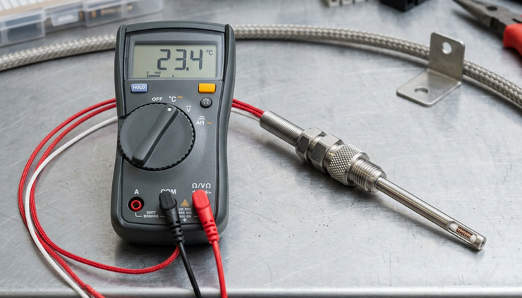
How a PT100 sensor measures temperature
A PT100 sensor uses the electrical behavior of platinum. Platinum is stable, resists corrosion, and has a repeatable relationship between temperature and resistance. That repeatability is the reason it works so well for accurate temperature measurement.
The name breaks down like this:
PT
The sensing material is platinum.
100
The sensor measures 100 ohms at 0 °C.
When temperature increases, resistance increases. When temperature decreases, resistance decreases. The measuring device sends a small current through the element, reads the voltage drop, calculates resistance, and converts that value to temperature using an RTD curve.
Most industrial PT100 sensors follow the IEC 60751 standard. A common version uses an alpha value of 0.00385 ohms per ohm per degree Celsius, often written as Pt100 385. This tells the instrument which resistance-to-temperature curve to use.
At a basic level, the relationship is easy to picture:
Temperature | Approximate PT100 resistance |
0 °C | 100.00 Ω |
100 °C | 138.5 Ω |
200 °C | 175.9 Ω |
These values are approximate and depend on the exact standard and tolerance class, but they show the key idea. The change is steady enough that a suitable instrument can translate resistance into a reliable temperature reading.
PT100 and PT1000 sensors are related but not identical
PT100 and PT1000 sensors work on the same principle. Both use platinum. Both increase resistance as temperature rises. The main difference is the base resistance at 0 °C.
Sensor type | Resistance at 0 °C | Typical use |
PT100 | 100 Ω | Industrial measurement, process control, high-accuracy systems |
PT1000 | 1,000 Ω | HVAC, battery systems, equipment monitoring, longer cable runs in some setups |
A PT1000 has ten times the resistance of a PT100. This affects how much cable resistance matters.
For example, if cable resistance adds 1 ohm to the measurement, that is a larger error for a 100-ohm PT100 than for a 1,000-ohm PT1000. Because of this, PT1000 sensors can be more forgiving in simple two-wire installations.
That does not mean PT1000 is always better. PT100 sensors remain very common because many industrial controllers, PLC input cards, transmitters, and calibration systems support them directly. They are also widely available in many probe styles and accuracy classes.
A short rule helps:
Use PT100 when the instrument is designed for it, high accuracy is needed, or an industrial standard setup already exists.
Use PT1000 when the system supports it and cable resistance needs to have less influence, especially in simpler installations.
Wiring has a direct effect on accuracy
The sensor element is only one part of the measurement loop. The wires between the sensor and the instrument also have resistance. If the instrument cannot separate wire resistance from sensor resistance, the reading will be too high.
This matters because RTD resistance changes are relatively small. With a PT100, about 0.385 ohms equals roughly 1 °C near 0 °C. A small wire resistance can create a visible temperature error.
Two-wire PT100 connections are simple but less accurate
A two-wire RTD uses one lead on each side of the sensor element. The instrument measures the resistance of the sensor plus the resistance of both wires.
That means the reading includes:
Sensor resistance
Lead wire resistance going out
Lead wire resistance coming back
Terminal and connection resistance
Two-wire connections can work for short cable runs where high accuracy is not needed. They also appear in low-cost equipment and compact installations. The weakness is clear: the instrument cannot tell the difference between the RTD element and the wiring.
If each wire contributes resistance, the measured temperature can read higher than the true process temperature. Longer cables, thinner conductors, and changing ambient conditions can increase the error.
Three-wire PT100 connections are the common industrial choice
A three-wire RTD adds a third lead so the instrument can compensate for lead resistance. This is the most common wiring method for industrial PT100 sensors.
In a typical three-wire circuit, the instrument assumes two of the lead wires have equal resistance. It uses the third wire to estimate and cancel lead wire error.
This works well when:
The three wires are the same type and gauge
The cable run uses the same length conductors
All conductors share the same environment
Terminations are clean and tight
Three-wire RTDs are a practical balance between accuracy, cost, and wiring effort. They are accurate enough for many process applications and easier to install than four-wire sensors.
The weak point is the assumption that the wire resistances match. If one conductor has different resistance because of length, gauge, corrosion, or a bad terminal, compensation will not be perfect.

Four-wire PT100 connections give the best lead compensation
A four-wire RTD uses separate pairs of wires for current and voltage measurement. The instrument drives current through one pair and senses voltage across the sensor with the other pair.
Because the voltage-sensing wires carry almost no current, their resistance has very little effect on the measurement. This method gives the best correction for lead resistance.
Four-wire PT100 sensors are often used in:
Calibration labs
Test benches
High-precision measurement systems
Long cable runs where accuracy matters
Applications where small temperature errors are costly
The tradeoff is more wiring and a measuring device that supports four-wire RTD input. For many industrial systems, three-wire is accurate enough. For reference measurements, four-wire is the better choice.
A PT100 needs the right input or a transmitter
A PT100 sensor does not generate a temperature signal by itself. It is a resistance element. The device connected to it must know how to measure RTD resistance and convert it into temperature.
That is why a dedicated RTD input matters.
A proper RTD input supplies a small excitation current, measures resistance accurately, applies the correct sensor curve, and handles the selected wiring method. Many controllers, PLC input modules, temperature indicators, and data loggers include RTD inputs.
When connecting a PT100 to an instrument, check these settings:
Sensor type is set to PT100, not thermocouple or PT1000
Curve or alpha value matches the sensor, often Pt100 385
Wiring mode matches the installation, such as 2-wire, 3-wire, or 4-wire
Temperature units are correct
Input range covers the expected process temperature
Any offset or calibration adjustment is intentional
A mismatch can cause confusing readings. A PT100 connected to an input set for PT1000 will not read correctly. A three-wire sensor configured as two-wire may include lead resistance that should have been compensated. A sensor curve mismatch can create smaller but still meaningful errors.
When a transmitter makes sense
An RTD transmitter converts the PT100 resistance signal into a standard output, often 4 to 20 mA or a digital signal. The transmitter may mount in the sensor head, in a field enclosure, or inside a control panel.
A transmitter is useful when:
The cable run to the control system is long
The PLC or controller does not have an RTD input
A standard 4 to 20 mA signal is easier to use
Electrical noise is a concern
The temperature range needs to be scaled for a specific process
The maintenance team wants easier device replacement
A transmitter does not make a poor installation accurate by magic. It still needs the correct RTD type, wiring, scaling, and placement. But it can reduce wiring problems and make the signal easier for a control system to handle.
For example, a PT100 in a tank might connect to a head-mounted transmitter. The transmitter reads the RTD locally, then sends a current signal back to the PLC. That current signal is usually less sensitive to cable resistance than sending the raw RTD signal over a long distance.

Probe design and placement affect the real reading
Even a perfectly wired PT100 can give a poor result if it measures the wrong spot. Temperature is not always uniform. Pipes, tanks, ovens, ducts, and machine parts can have gradients, hot spots, cold spots, and lag.
The probe should sit where the process temperature represents the value being controlled or monitored.
In a pipe, this often means placing the probe tip into the flow, not just near the pipe wall. In a tank, it may mean avoiding dead zones or areas near heaters, inlets, or cooling jackets unless those are the points of interest. In air measurement, it means keeping the sensor away from radiant heat, direct drafts, and surfaces that skew the reading.
Common placement issues include:
The probe tip does not reach the process medium
The thermowell is too large or poorly fitted
The sensor sits too close to a wall or fitting
Heat conducts through the probe stem from another area
Air pockets or poor contact affect surface measurements
The sensor response time is too slow for the process
A thermowell protects the sensor and allows replacement without opening the process. It also adds thermal mass, which slows response. In fast-changing processes, this lag can matter.
For surface measurements, contact quality is critical. A PT100 clamped to a metal pipe will not read the same as one inserted into the fluid. Insulation, thermal paste, spring loading, and mounting pressure can all change the result.
Accuracy depends on more than the sensor class
PT100 sensors come in tolerance classes. Common classes include Class B, Class A, and tighter grades used for higher accuracy. The class describes the allowable sensor element error under defined conditions.
But the final reading includes more than the sensor element. A complete measurement has several possible error sources:
Error source | How it affects the reading |
Sensor tolerance | The RTD element may vary within its accuracy class |
Lead resistance | Extra resistance can make temperature read high |
Instrument accuracy | The input module or indicator has its own uncertainty |
Wiring configuration | Two-wire, three-wire, and four-wire methods handle cable resistance differently |
Self-heating | Excitation current can warm the RTD slightly |
Probe placement | The sensor may not be measuring the intended temperature |
Thermal contact | Poor contact can cause lag or offset |
Configuration | Wrong sensor type, curve, or wiring setting creates errors |
Self-heating happens because the measuring current creates a small amount of heat in the RTD element. In most industrial systems this is minor, but it can matter in still air or low-mass probes. A good RTD input uses a suitable excitation current to reduce this effect.
Cable quality also matters. Shielding can help in noisy environments, especially near motors, drives, and switching equipment. The shield should follow the instrument manufacturer’s grounding guidance. Poor grounding can introduce noise instead of reducing it.
A PT100 measurement is only as good as the full loop: sensor, cable, input, configuration, and installation.
Practical checks before commissioning a PT100 loop
A few simple checks can prevent hours of troubleshooting later.
Before power-up, confirm the sensor and instrument match. A PT100 probe should connect to an RTD input or transmitter that supports PT100. The wiring terminals should match the selected two-wire, three-wire, or four-wire layout.
Then verify the cable. Use the same conductor type and length for three-wire circuits. Keep RTD wiring away from high-current power cables where possible. Check terminals for tightness and corrosion.
Next, check the configuration. The instrument should be set for the correct RTD type, wiring mode, units, and range. If a transmitter is used, confirm the low and high temperature values match the control system scaling.
A quick field test can also help. At room temperature, a PT100 should measure a little above 100 ohms, depending on the actual ambient temperature. If the resistance is far outside the expected range, look for an open circuit, short circuit, wrong sensor type, or wiring error.
For a three-wire PT100, compare lead resistances if the reading seems wrong. Unequal lead resistance can create error. For a two-wire PT100, account for cable resistance or use a lead compensation setting if the instrument provides one.

Key takeaway
A PT100 sensor is a reliable way to measure temperature, but the sensor element is only the starting point. It works by tracking the predictable change in platinum resistance, with 100 ohms at 0 °C as the reference point.
For basic installations, two-wire wiring may be enough. For most industrial work, three-wire wiring gives a better balance of accuracy and practicality. For precision measurement, four-wire wiring provides the best correction for lead resistance.
The right input matters too. A PT100 needs an RTD-capable instrument or a transmitter that is correctly configured for the sensor type, curve, wiring method, and temperature range.
If a reading looks wrong, do not blame the probe first. Check the full measurement loop: sensor type, wiring, cable resistance, input settings, transmitter scaling, probe position, and thermal contact. That full-loop view is what turns a PT100 from a simple resistance element into a dependable temperature measurement.


Comments