
PLC Analogue Inputs Guide 4–20 mA 0–10 V RTD and Thermocouple Wiring
A PLC can only control what it can measure. If a pressure transmitter, flow meter, level sensor, or temperature probe is wired to the wrong input type, the value on the screen may drift, jump, read backwards, or show nothing at all.
Analogue inputs are the bridge between real-world process conditions and PLC logic. They convert variable electrical signals into numbers the controller can use for alarms, interlocks, trends, PID loops, and operator displays.
This guide explains the common PLC analogue input types used in industrial automation: 4-20 mA current loops, 0-10 V voltage signals, RTDs, and thermocouples. It also covers active and passive loop wiring, input modules, signal scaling, shielding, grounding, and practical examples.

PLC analogue inputs convert process signals into usable values
A digital input tells a PLC whether something is on or off. An analogue input tells the PLC how much of something is present.
Typical analogue measurements include:
Pressure in a pipe or vessel
Flow rate through a line
Tank level
Temperature in an oven, tank, or process skid
Position from a valve or actuator
Speed from a drive reference or tachometer output
The PLC input module reads an electrical signal, then converts it into a raw count. The PLC program scales that count into an engineering value such as bar, litres per minute, percent, degrees Celsius, or millimetres.
Common signal types include the following.
Signal type | Common use | Typical field device |
4-20 mA | Industrial process transmitters | Pressure transmitters, flow meters, level sensors |
0-10 V | Short-run control signals | Drives, valve positioners, small sensors |
RTD | Accurate temperature measurement | Pt100 or Pt1000 temperature probes |
Thermocouple | High-temperature measurement | Furnace, exhaust, kiln, or process probes |
The input module must match the signal. A 4-20 mA transmitter should connect to a current input. A Pt100 RTD should connect to an RTD module or temperature input designed for resistance measurement. A thermocouple should connect to a thermocouple input with cold junction compensation.
4-20 mA current loops are the industrial standard
The 4-20 mA signal is widely used because it works well over long cable runs and is less sensitive to voltage drop than voltage signals. The current in the loop represents the process value.
For example, a pressure transmitter ranged from 0 to 10 bar might output:
Process pressure | Loop current |
0 bar | 4 mA |
5 bar | 12 mA |
10 bar | 20 mA |
The live zero at 4 mA is useful. If the wire breaks, the signal usually drops below 4 mA, which helps the PLC detect a fault instead of mistaking it for a valid zero reading.
Passive 4-20 mA transmitters need loop power
Many industrial transmitters are 2-wire passive devices. They do not generate their own loop power. They regulate the current drawn from an external DC supply, often 24 VDC.
A typical passive pressure transmitter loop includes:
24 VDC power supply
Pressure transmitter
PLC analogue current input
Return path to 0 V
A simplified loop looks like this:
`+24 VDC -> transmitter + -> transmitter - -> PLC analogue input + -> PLC analogue input - -> 0 VDC`
Some PLC input cards provide loop power at the terminal. Others require a separate power supply. Always check the module wiring diagram before connecting the field device.
Active 4-20 mA instruments provide the current signal
An active 4-20 mA output supplies or drives the loop current itself. This is common on some powered flow meters, signal conditioners, and analysers.
In this case, the PLC input usually acts as the load. You do not add a second loop supply unless the manual specifically says to. Adding power to an active output can damage equipment.
A useful rule is simple:
Passive transmitter Needs external loop power
Active transmitter Sends current to the PLC input
Passive PLC input Measures current but does not power the loop
Active PLC input Provides loop power for passive field devices
The safest approach is to identify which side sources power and which side receives the signal.
Common 4-20 mA examples
A pressure transmitter on a compressed air header might send 4-20 mA for 0 to 16 bar. The PLC scales the signal and triggers a low-pressure alarm if the value falls below the required operating band.
An electromagnetic flow meter on a water line might send 4-20 mA for 0 to 500 litres per minute. The PLC can totalise flow, display live rate on an HMI, and stop a pump if flow is too low.
An ultrasonic level sensor over a tank might send 4-20 mA for 0 to 5 metres. The PLC can convert that height into percent full, start a transfer pump, and alarm on high level.

0-10 V signals work best over short, clean cable runs
A 0-10 V signal changes voltage in proportion to the measured value or command. It is common in HVAC controls, small machines, analogue speed references, valve commands, and some compact sensors.
For example, a level sensor ranged from 0 to 2 metres might output:
Tank level | Voltage |
0 m | 0 V |
1 m | 5 V |
2 m | 10 V |
Voltage signals are easy to understand, but they are more affected by electrical noise, cable resistance, and grounding issues. For longer industrial cable runs, 4-20 mA is usually the better choice.
Use 0-10 V when:
The cable run is short
The signal source and PLC share a clean reference
The environment has limited electrical noise
The equipment manual specifies a voltage input or output
Avoid running 0-10 V signals alongside motor cables, contactor wiring, heater circuits, or variable speed drive outputs. If the signal must pass through a noisy area, use screened cable and separate the route from power wiring.
0-10 V wiring points
A 0-10 V signal normally needs a signal wire and a common reference. The PLC measures voltage between the analogue input terminal and analogue common.
Check whether the input is single-ended or differential.
A single-ended input measures each channel against a shared common. It is simple, but common wiring must be clean.
A differential input measures the voltage between two input terminals for that channel. It can reject some common-mode noise and is often better for industrial signals.
Never assume that 0 V, analogue common, DC negative, and protective earth are all the same point. The panel design should define how commons are bonded and where shields terminate.
RTDs measure temperature through resistance
An RTD, or resistance temperature detector, changes resistance as temperature changes. The most common industrial type is the Pt100, which has a resistance of 100 ohms at 0 °C. Pt1000 probes are also used and have 1,000 ohms at 0 °C.
RTDs are often chosen for process temperatures where accuracy and stability matter, such as:
Water temperature in a heat exchanger
Product temperature in a food process vessel
Bearing temperature on rotating equipment
Tank temperature in a chemical process
Air temperature in an environmental chamber
RTDs do not produce a voltage or current signal by themselves. The input module sends a small measuring current through the sensor and reads the resistance. That is why RTDs need an RTD input module or a temperature transmitter.
2-wire, 3-wire, and 4-wire RTDs
Lead resistance affects RTD accuracy. A long cable adds resistance, which can make the temperature read higher than it really is.
RTD wiring | How it is used | Practical note |
2-wire | Short cable runs, lower accuracy needs | Lead resistance adds error |
3-wire | Common industrial choice | Compensates for lead resistance when wires match |
4-wire | Higher accuracy measurement | Best compensation, more terminals needed |
For many plant applications, 3-wire Pt100 wiring gives a good balance of accuracy and simplicity. Use the same cable type and conductor size for all RTD leads so the compensation works correctly.
RTD transmitter option
Instead of wiring the RTD directly to a PLC temperature module, a head-mounted or DIN rail temperature transmitter can convert the RTD signal to 4-20 mA.
That can be a good choice when:
The PLC has standard current inputs but no RTD module
The RTD is far from the control panel
Electrical noise is a concern
Maintenance teams prefer standard 4-20 mA loops
The temperature range needs local configuration
For example, a Pt100 probe in a hot water tank can connect to a temperature transmitter ranged 0 to 100 °C. The transmitter sends 4-20 mA to the PLC, and the PLC scales it like any other current loop.
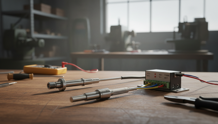
Thermocouples are suited to higher temperatures
A thermocouple uses two dissimilar metals joined at a measuring junction. When there is a temperature difference between the measuring junction and the reference junction, it produces a small voltage.
Common thermocouple types include J, K, T, and N. Type K is widely used for general industrial high-temperature applications.
Thermocouples are often used for:
Furnaces and ovens
Kilns and dryers
Exhaust temperature
Heat treatment equipment
Plastic processing machinery
Boiler and burner systems
Thermocouple signals are very small, so wiring practice matters. Use the correct thermocouple extension cable for the thermocouple type. Do not replace it with ordinary copper cable unless a suitable transmitter or terminal arrangement allows it.
Cold junction compensation matters
A thermocouple input needs cold junction compensation. The PLC input module or transmitter measures the temperature at the terminal connection and uses that value to calculate the real process temperature.
If the wrong thermocouple type is selected in the PLC hardware configuration, the displayed temperature can be badly wrong. If the polarity is reversed, the reading may move down when the process heats up.
Thermocouple connectors and cables are normally colour coded, but colour codes can vary by region and standard. Confirm the cable type and polarity from the supplier documentation.
Analogue input modules must match the field signals
PLC analogue input modules are not all the same. Some accept current only, some voltage only, some are universal, and some are dedicated to RTD or thermocouple measurement.
Before selecting a module, check these items:
Signal type
Number of channels
Isolated or non-isolated channels
Input resolution
Supported sensor types
Power supply requirements
Wiring method
Diagnostic features
PLC platform compatibility
Isolation deserves attention. Isolated analogue inputs help reduce problems caused by ground potential differences and electrical noise. They are useful when signals come from different parts of a plant, from separate power supplies, or from instruments connected to grounded pipework.
A non-isolated module can work well in a compact machine with short wiring and a common control supply. In larger installations, isolated inputs or signal isolators can prevent hard-to-find measurement problems.
Universal inputs can simplify spares
Universal analogue modules can often be configured for current, voltage, RTD, or thermocouple signals. They reduce the number of spare module types needed, but they still require careful configuration and correct terminal wiring.
If a plant has many standard 4-20 mA transmitters, dedicated current input cards may be more cost-effective. If machines vary from project to project, universal input cards can make panel design more flexible.
Signal scaling turns raw counts into engineering units
The PLC does not automatically know that 12 mA means 5 bar or that 7.5 V means 75 percent. The program must scale the raw input into a useful value.
A simple linear scaling formula is:
`Engineering value = ((Raw value - Raw low) / (Raw high - Raw low)) × (Engineering high - Engineering low) + Engineering low`
For a 4-20 mA pressure transmitter ranged 0 to 10 bar:
4 mA equals 0 bar
20 mA equals 10 bar
12 mA equals 5 bar
Many PLC platforms provide scaling blocks, analogue input function blocks, or built-in engineering unit configuration. Use these where available, but still document the range clearly.
Good scaling practice includes:
Set the sensor range in the instrument and PLC to match
Clamp values only after fault detection
Keep raw values available for troubleshooting
Add filtering where needed, but do not hide real process changes
Use sensible decimal places on the HMI
Display engineering units clearly
For a flow meter, scaling might convert 4-20 mA into 0 to 1,000 litres per minute. The PLC can then calculate total flow by integrating the rate over time.
For a level transmitter, scaling may convert 4-20 mA into 0 to 100 percent. If the tank shape is not linear, the PLC or HMI may need a lookup table to convert level height into volume.
Good wiring prevents most analogue faults
Many analogue problems come from wiring rather than programming. A signal that looks unstable in the PLC may come from poor shielding, shared commons, loose terminals, incorrect cable routing, or mismatched input settings.
Follow these practical wiring habits.
Use screened instrument cable for low-level analogue signals. For most applications, terminate the shield at one end only, usually at the control panel earth bar, unless the site standard or equipment manual specifies another method.
Separate analogue cables from power cables. Keep signal wiring away from variable speed drive outputs, motor feeders, contactor coils, and high-current switching circuits. Cross power cables at right angles where separation is not possible.
Keep polarity consistent. Current loops and thermocouples are polarity sensitive. Reversed polarity is a common commissioning fault.
Use ferrules and clear wire numbers. Analogue troubleshooting is much easier when every conductor matches the drawing.
Check input configuration. A universal input set to voltage will not read a current loop correctly. A thermocouple input set to Type J will not correctly read a Type K probe.
Document ranges at the device, PLC, and HMI. If a pressure transmitter is changed from 0 to 10 bar to 0 to 16 bar, the PLC scaling and HMI display must change too.

Signal interface hardware solves difficult connections
Not every field signal connects neatly to a PLC input. Signal-interface hardware can adapt, protect, or clean up the signal.
Common interface devices include:
Device | What it does | Typical use |
Signal isolator | Passes a signal across an isolation barrier | Reducing ground loop problems |
Signal splitter | Sends one input to two outputs | PLC and local display from one transmitter |
Temperature transmitter | Converts RTD or thermocouple to 4-20 mA | Long cable runs or standard PLC current inputs |
Loop-powered indicator | Displays process value in the field | Local pressure, flow, or level display |
Intrinsic safety barrier | Limits energy into hazardous areas | Instruments in classified zones |
Surge protector | Helps protect signal circuits | Long outdoor cable runs |
For example, a remote tank level transmitter may suffer from unstable readings because the tank farm and control panel have different earth potentials. A 4-20 mA signal isolator can break the unwanted path while passing the measurement to the PLC.
A thermocouple on a furnace can connect to a temperature transmitter near the process. The transmitter sends a stronger 4-20 mA signal back to the PLC panel, which can be easier to install and maintain.
ProSense Instruments can supply the full measurement chain
A reliable analogue input system needs more than one correct part. The field sensor, cable, signal interface, PLC input module, PLC program, and HMI display all need to work together.
ProSense Instruments can help specify and supply equipment for industrial control applications, including:
Pressure transmitters for air, water, hydraulic, and process use
Flow meters for monitoring liquid or gas flow
Level sensors for tanks, vessels, and sumps
RTD and thermocouple temperature probes
Temperature transmitters and signal conditioners
Signal isolators, splitters, and interface modules
PLC and HMI equipment for machine and process control
Panel components and supporting automation hardware
This joined-up approach helps avoid mismatched hardware. A pressure transmitter can be selected with the right range, process connection, electrical output, and PLC input module. A temperature probe can be supplied with the correct transmitter, cable type, and HMI scaling requirements.
When building or upgrading a control system, define the measurement first. Then choose the sensor output, input module, interface hardware, and scaling method as one system.
A practical checklist for commissioning analogue inputs
Before signing off a PLC analogue input, test the full path from the field device to the HMI.
Use this checklist:
Confirm the instrument tag matches the drawing
Check the sensor range and output type
Verify loop supply voltage and polarity
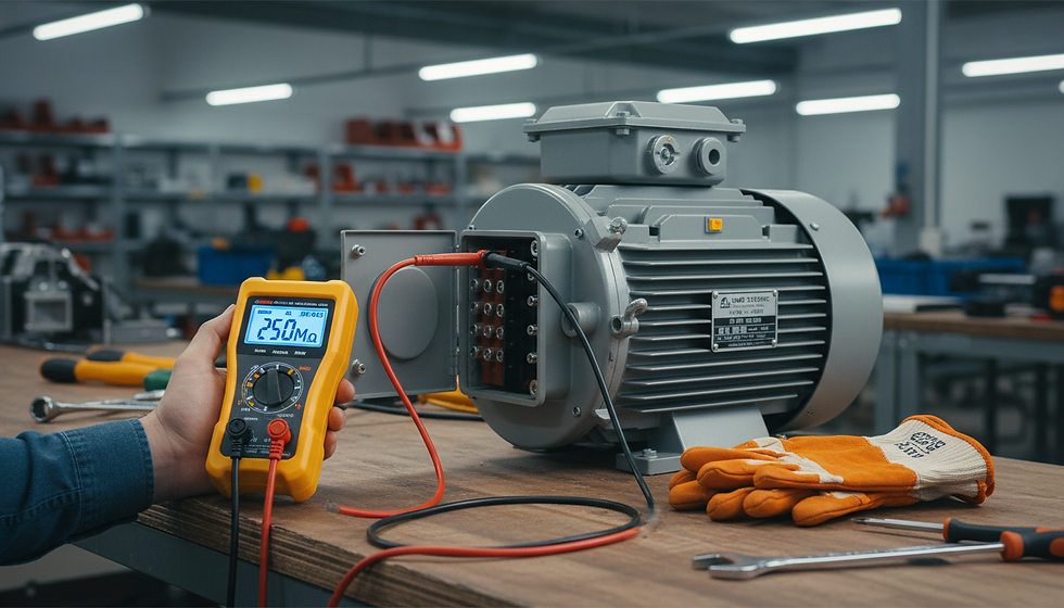
Measure the signal with a suitable meter or loop calibrator
Confirm PLC input configuration
Check raw counts in the PLC
Verify scaling at low, mid, and high points
Confirm HMI units and decimal places
Test alarm thresholds and fault detection
Record final settings for maintenance
For current loops, a loop calibrator can simulate 4 mA, 12 mA, and 20 mA. For voltage inputs, a signal source can inject 0 V, 5 V, and 10 V. For temperature inputs, use a suitable RTD or thermocouple simulator where accuracy matters.
The best PLC analogue inputs are boring in the best way. The values are stable, the units make sense, faults are detected, and maintenance teams can trace the signal without guesswork. Start with the right sensor, match the input module, wire it cleanly, and scale it clearly. That is the foundation of dependable industrial control.

Comments