
Hipot Testing vs Insulation Resistance Testing Key Differences and Best Practices
A cable can show excellent megohm readings and still fail when exposed to a high-voltage withstand test. A motor winding can pass a dielectric withstand test and still show a declining insulation trend over months of service. That is why hipot testing and insulation resistance testing are often mentioned together, but they do not answer the same question.
Both tests evaluate insulation integrity. Both help reduce shock, fire, arc flash, and equipment failure risk. The difference is in what they stress, what they measure, and how the results should be interpreted.
Insulation resistance testing measures how much an insulation system resists DC leakage current. Hipot testing verifies whether that insulation can withstand a specified high voltage without breakdown. One is mainly diagnostic and trend-based. The other is mainly a proof or withstand test.

What insulation resistance testing measures
Insulation resistance testing applies a DC voltage between conductors, or between a conductor and ground, then measures the resulting leakage current. The instrument calculates resistance using Ohm’s law and reports the value in megohms, gigohms, or higher.
The core question is simple:
How well does the insulation resist leakage at the applied test voltage?
A high resistance value usually indicates dry, clean, intact insulation. A low or falling value can point to moisture, contamination, carbon tracking, thermal aging, mechanical damage, or incorrect installation.
The test current is not a single clean value. It commonly includes:
Capacitive charging current
Current that flows while the insulation system charges like a capacitor.
Absorption current
Current related to dielectric polarization inside the insulation material.
Conduction or leakage current
Current that continues through or across the insulation after charging effects settle.
For this reason, timing matters. A one-minute insulation resistance reading is common, but some assets benefit from longer readings, dielectric absorption ratio, or polarization index testing. Motors, generators, transformers, and long cable runs often show more useful information when readings are tracked over time rather than judged from one isolated value.
IR testing is especially valuable because it is usually non-destructive when performed at the correct test voltage. It gives maintenance teams a practical way to monitor insulation condition without applying the much higher stresses used in a withstand test.
What hipot testing measures
Hipot is short for high potential. A hipot test applies a voltage above normal operating voltage between conductive parts that should remain electrically isolated. The purpose is to confirm that the insulation system can withstand a defined electrical stress for a specified time.
The core question is different from IR testing:
Can the insulation survive the specified overvoltage without breakdown or excessive leakage?
A hipot tester may apply AC or DC voltage, depending on the equipment, standard, and test objective. During the test, the instrument monitors current and looks for failure conditions such as dielectric breakdown, flashover, arc tracking, or leakage above the programmed limit.
Hipot testing is common in manufacturing, repair validation, commissioning, and compliance programs because it provides a clear pass or fail result. It helps confirm that creepage distances, clearances, insulation barriers, wire routing, and assembly quality are adequate.
The test can reveal defects that a routine resistance check may not expose, such as:
Pinched wire insulation inside an enclosure
Inadequate spacing between live parts and grounded metal
Weak insulation that only fails under elevated voltage
Contamination paths across insulating surfaces
Damage caused during assembly, transport, or repair
Hipot testing must be treated with more caution than insulation resistance testing. The applied voltage is intentionally high. On some insulation systems, especially aged or marginal assets, the test can worsen an existing weakness or cause failure. That risk is not a flaw in the test, but it does mean the test level and method must match the asset and the governing standard.

Key differences between the two tests
Hipot Testing vs Insulation Resistance Testing Key Differences and Best Practices starts with recognizing that the tests complement each other rather than compete with each other. They use different voltage levels, produce different types of results, and fit different points in the asset life cycle.
Test characteristic | Insulation resistance testing | Hipot testing |
Main purpose | Measures insulation resistance and leakage behavior | Verifies dielectric withstand capability |
Typical output | Quantitative resistance value, often trended over time | Pass or fail result, often with leakage current limit |
Test voltage | DC voltage selected for equipment rating and insulation class | Elevated AC or DC voltage specified by standard or procedure |
Stress level | Moderate when correctly selected | Higher electrical stress by design |
Main use | Maintenance diagnostics, troubleshooting, condition assessment | Production testing, commissioning, repair validation, compliance |
Risk to weak insulation | Low to moderate | Higher, especially on aged or contaminated assets |
Best value | Shows degradation trends | Confirms ability to withstand overvoltage |
A useful way to separate them is to think in terms of measurement versus proof.
IR testing measures insulation condition. It helps answer whether an asset is clean, dry, and stable enough for service or further testing. Hipot testing proves that the insulation barrier can tolerate a defined voltage stress without failing.
That distinction matters in the field. A high IR value does not guarantee a hipot pass. For example, a small air gap or sharp conductor edge may not reduce the insulation resistance reading much, but it can initiate partial discharge or flashover under high voltage. By contrast, an asset may pass hipot yet still have lower-than-expected IR readings due to surface contamination that should be cleaned and monitored.
Why both tests matter for electrical safety
Electrical insulation is one of the main barriers between energized conductors and people, grounded metal, control circuits, and nearby equipment. When that barrier fails, the result can be shock, equipment damage, ground faults, nuisance trips, thermal events, or arc flash conditions.
Insulation resistance testing supports safety by identifying deterioration before it becomes a fault. It is a practical tool for preventive maintenance because readings can be repeated under similar conditions and compared over time. A steady downward trend often gives advance warning, especially in equipment exposed to moisture, heat, vibration, oil, dust, or chemicals.
Hipot testing supports safety by challenging the insulation barrier at a known stress level. It helps catch gross defects before equipment is shipped, placed into service, or returned after repair. This is critical for products and assemblies where a single wiring error or spacing issue can create a touch voltage hazard.
Together, the tests create a stronger safety picture:
IR testing checks condition before energization or during maintenance.
Hipot testing checks withstand strength against defined voltage stress.
IR testing can be used before and after hipot to detect changes caused by the withstand test.
Recorded results support traceability for quality, commissioning, and maintenance programs.
Neither test replaces visual inspection, continuity checks, ground bond testing, functional testing, or thermal evaluation. Insulation failures often involve mechanical, environmental, and electrical factors. The best safety programs combine test data with inspection and operating history.
When insulation resistance testing is the better choice
Insulation resistance testing is often the first electrical insulation test performed after lockout, visual inspection, and verification of absence of voltage. It is well suited to condition assessment because it gives a numerical result that can be compared against previous readings.
Common scenarios include the following.
Preventive maintenance on motors and generators
Motors in damp, dirty, or high-temperature areas benefit from periodic IR testing. A maintenance team can compare readings phase to phase and phase to ground, then track changes across months or years.
The absolute number matters, but the trend often matters more. A motor that drops steadily from very high resistance to a much lower value under similar temperature and humidity conditions deserves attention before it trips a feeder or fails in service.
Cable testing before energization
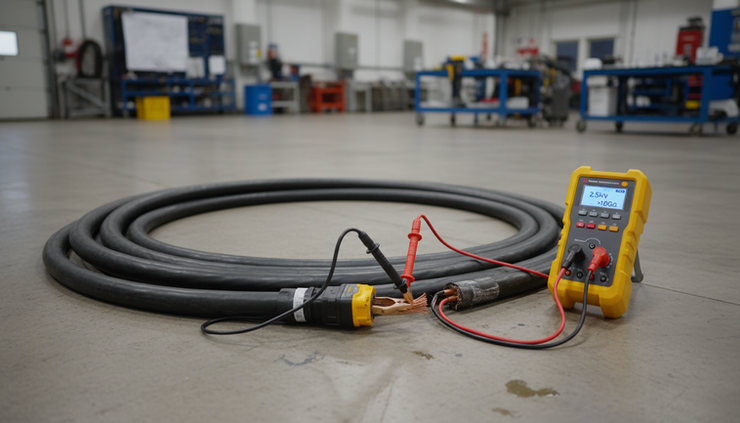
Newly installed or repaired cables should be checked for insulation damage before energization. IR testing can reveal crushed insulation, moisture intrusion, or termination errors. It is especially useful after pulling cables through conduit, installing splices, or completing terminations.
For long cable runs, capacitance affects charging time. Test duration, discharge time, and stable readings become more important.
Troubleshooting nuisance trips
Ground-fault trips, unexplained fuse operation, or intermittent leakage can be linked to insulation issues. IR testing helps isolate the problem by testing circuits section by section.
Loads and sensitive electronics should be disconnected when required by the procedure, since the test voltage can damage components not designed for it.
Checking equipment after storage
Transformers, motors, heaters, switchgear, and portable equipment may absorb moisture during storage. IR readings before energization help confirm whether drying, cleaning, or further inspection is needed.
When hipot testing is the better choice
Hipot testing is used when the goal is to confirm dielectric withstand capability against a specified requirement. It is common where standards, customer specifications, or quality procedures require a formal pass or fail test.
Production testing of electrical equipment
Manufacturers use hipot testing to verify insulation barriers in finished products. This can include appliances, power supplies, transformers, control panels, cable assemblies, and industrial equipment.
The test can catch assembly defects that visual inspection may miss, such as a conductor trapped under a cover, a damaged sleeve, or insufficient spacing near a grounded chassis.
Commissioning new assemblies
Before energizing new switchboards, control panels, transformers, or cable systems, a withstand test may be required by project specifications or applicable standards. The test helps confirm that installation work did not compromise insulation integrity.
Commissioning procedures should define which circuits are included, which components are disconnected, and which test voltage and duration apply.
Verifying repairs or rewinds
Motor rewinds, transformer repairs, and cable splice repairs often call for a dielectric withstand test. The goal is to confirm that the repaired insulation system can tolerate the required stress before the equipment returns to service.
A lower-level IR test is commonly performed first. If IR readings are poor, applying a hipot test may be unsafe or unsuitable until the cause is addressed.
Compliance and safety certification
Many products must pass dielectric strength requirements before sale or use. The exact voltage, duration, leakage limit, and test method come from the applicable product safety standard. In these cases, hipot testing is part of documented quality control, not just troubleshooting.
Best practices for insulation resistance testing
Good IR testing depends on consistency. The readings are only useful when the test setup, voltage, duration, and environmental conditions are controlled.
Use these practices as a baseline:
De-energize and isolate the equipment
Apply proper lockout procedures, verify absence of voltage, and isolate the circuit from connected equipment where required.
Select the correct test voltage
Use the equipment rating, insulation class, manufacturer instructions, and site procedure. Excessive voltage can damage sensitive components.
Record temperature and humidity
Insulation resistance changes with environmental conditions. Temperature correction may be needed when comparing readings.
Allow the reading to stabilize
Large motors, transformers, and cables can take time to charge. A one-minute reading is common, but longer tests may give better diagnostic value.
Use the guard terminal when appropriate
Guarding can reduce the effect of surface leakage and help evaluate the insulation volume more accurately.
Discharge the asset after testing
Cables, windings, and capacitive equipment can retain charge. Use the tester’s discharge function and verify safe voltage before touching conductors.
Documentation should include asset identification, test voltage, test duration, measured value, temperature, humidity, connection points, and any unusual observations. Without that context, future comparison becomes less reliable.
Best practices for hipot testing
Hipot testing requires strict procedural control because the test intentionally applies hazardous voltage. The safest and most useful tests are planned before the start button is pressed.
Key practices include:
Follow the applicable standard or written procedure
Do not guess the voltage or dwell time. Use the product standard, engineering specification, manufacturer guidance, or approved site procedure.
Inspect before applying high voltage
Look for loose strands, damaged insulation, contamination, sharp edges, missing barriers, and incorrect grounding.
Perform an IR test first when appropriate
Poor insulation resistance may indicate that the asset is not ready for dielectric withstand testing.
Control the test area
Use barriers, warning signs, interlocks, and trained personnel. Keep unauthorized people away from the equipment under test.
Ramp voltage when the procedure allows it
A controlled ramp can reduce nuisance trips from charging current and gives the operator better visibility into leakage behavior.
Set leakage limits correctly
Leakage current varies with capacitance, test voltage, frequency, and equipment design. Limits should come from the relevant requirement, not from habit.
Discharge after DC hipot testing
DC testing can leave significant stored charge in capacitive assets. Discharge and verify before handling.
AC and DC hipot methods are not interchangeable without engineering review. AC testing stresses the insulation with alternating polarity and includes capacitive current. DC testing produces lower steady-state charging current on capacitive loads, but it polarizes insulation differently. The correct method depends on the asset and the requirement.

Common mistakes that reduce test value
Even experienced teams can get poor data from good instruments. The most common problems are procedural, not technical.
One frequent mistake is treating an IR reading as a universal pass or fail value without context. A value that is acceptable for one asset may be questionable for another. Cable length, insulation material, temperature, and equipment type all affect the reading.
Another mistake is leaving connected electronics in the circuit. Control boards, surge protective devices, filters, sensors, and variable frequency drives may not tolerate insulation test voltages or hipot voltages. Procedures should state what must be disconnected and what may remain connected.
Poor discharge practice is also a serious issue. Long cables and large windings can store energy after testing. Touching conductors too soon can create a shock hazard even after the instrument has been turned off.
For hipot testing, one of the biggest errors is applying a generic voltage because “that is what we always use.” Dielectric test levels should not be chosen by tradition. They should come from the relevant standard, design requirement, or approved engineering procedure.
How to choose the right test sequence
A practical sequence often looks like this:
Review drawings, nameplates, procedures, and applicable requirements.
De-energize, isolate, lock out, and verify absence of voltage.
Inspect the equipment and correct visible defects.
Perform insulation resistance testing.
Evaluate whether results support further testing.
Conduct hipot testing if required and appropriate.
Discharge the equipment and verify safe voltage.
Repeat IR testing if the procedure calls for comparison.
Record all results with conditions and connection details.
This sequence helps avoid applying high voltage to equipment that already shows signs of poor insulation condition. It also creates before-and-after data that can reveal whether a withstand test changed the insulation state.
For many maintenance tasks, IR testing alone may be enough. For production release, compliance verification, and certain commissioning activities, hipot testing may be mandatory. The best choice comes from the test objective, asset condition, and applicable requirement.
The practical takeaway
Insulation resistance testing and hipot testing both protect people and equipment, but they do it in different ways. IR testing measures leakage behavior and supports condition-based maintenance. Hipot testing applies a defined overvoltage to prove dielectric withstand strength.
Use insulation resistance testing when the goal is diagnosis, trending, troubleshooting, or pre-checking an asset before energization. Use hipot testing when the goal is formal dielectric proof, production quality control, commissioning verification, or repair acceptance.
The strongest electrical safety programs do not treat these tests as interchangeable. They use each one where it fits, document the results, respect the hazards, and make decisions based on the equipment, the environment, and the standard that applies.


Comments