
Hipot Testing for Switchboards and Control Panels Safety Compliance and Documentation Best Practices
A completed switchboard or control panel can look perfect and still hide an insulation fault. A nicked conductor, pinched wire, loose strand, metal shaving, incorrect spacing, moisture, or assembly damage may not show up during a visual inspection. Under normal operating voltage, that weakness might stay quiet. Under stress, it can become a flashover, nuisance trip, damaged component, or serious safety event.
That is why dielectric withstand testing, often called hipot testing, remains a key final verification step for many completed electrical assemblies. It helps confirm that insulated parts, barriers, wiring, devices, and enclosure structures can withstand a specified test voltage without breakdown.
For technicians, panel builders, commissioning teams, and quality personnel, the test itself is only part of the job. The real value comes from testing the right way, protecting sensitive electronics, controlling risk, and producing records that stand up to customer, inspector, and internal quality review.

Why dielectric testing matters after panel assembly
Dielectric testing checks whether insulation systems can withstand an elevated voltage between conductive parts that should remain electrically separated. In a completed switchboard or control panel, this usually means testing between live circuits and grounded metal parts, or between isolated circuits where the applicable design or standard requires it.
The goal is not to “prove” the equipment will never fail. It is to catch assembly and insulation defects before the panel is energized in service.
Common problems found during final dielectric testing include:
Damaged insulation from pulling, stripping, routing, or clamping conductors
Wire strands touching grounded metal or adjacent terminals
Incorrectly installed barriers or insulating boots
Reduced clearance from hardware, bus supports, or field wiring areas
Conductive debris left after drilling, tapping, or punching
Moisture, dust, or contamination on insulating surfaces
Miswired surge devices, filters, transformers, or power supplies
Components installed with lower voltage ratings than the assembly requires
A visual check and point-to-point wiring inspection may catch many of these issues. Hipot testing adds a different kind of stress. It applies a voltage higher than normal service voltage for a defined duration. If insulation is weak, the test can reveal it before a customer does.
That matters for several reasons.
Personnel safety improves because insulation failures can place touchable metal parts at hazardous voltage. Grounding and bonding checks are essential, but dielectric testing helps confirm that live parts are separated from grounded structures as designed.
Equipment reliability improves because faults found in the shop cost less to correct than faults found after installation. A failed test may be inconvenient, but it is far better than a failure during startup.
Compliance support improves because many product standards, customer specifications, and quality programs expect dielectric withstand verification as part of final inspection. Depending on the equipment type and jurisdiction, references may include standards such as UL 891, UL 508A, IEC 61439, CSA requirements, the National Electrical Code, and site-specific specifications.
The exact test voltage, test duration, leakage criteria, and circuits to be tested should come from the applicable standard, project specification, equipment rating, and manufacturer instructions. Guessing is not acceptable. A 480 V motor control panel, a low-voltage distribution switchboard, and a panel with electronic power supplies may not be tested in the same way.
What to verify before applying test voltage
A clean, controlled setup reduces false failures and keeps the test safe. Before applying test voltage, confirm that the panel is ready for dielectric testing rather than still in an assembly state.
A practical pre-test review should include the following checks.
Mechanical completion
All covers, barriers, insulators, bus supports, terminal covers, and guarding needed for the test condition should be installed. If the panel is tested with temporary access covers removed, confirm that the test still represents the intended insulation paths and does not create artificial clearances.
Cleanliness
Remove metal shavings, stripped insulation, wire ties, loose hardware, labels, and packing debris. Conductive dust and metal chips can create leakage paths or unexpected breakdown points.
Grounding and bonding
Verify protective bonding before dielectric testing. Ground conductors, bonding jumpers, doors, gland plates, and enclosure sections should have continuity where required. A hipot test should not be used as a substitute for a bonding check.
Correct circuit grouping
Identify which circuits will be tied together for the test and which will be excluded or isolated. For example, line and load conductors may be connected together during a test to stress insulation to ground, depending on the procedure. Control circuits, communication circuits, and low-voltage electronics may need a separate approach.
Test equipment condition
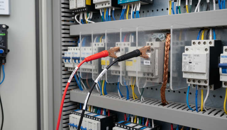
Use a dielectric tester with the correct voltage capability, current limit, ramp function, metering, and trip settings for the job. Confirm that the tester has a current calibration label or calibration record within the required interval. Inspect leads, clamps, probes, and return connections for damage.
Environmental conditions
Wet, dusty, or unconditioned environments can affect results. If a panel has been stored cold and then moved into a warmer space, condensation may form. Allow the assembly to stabilize and dry before testing.
How to isolate sensitive electronics during testing
Modern switchboards and control panels often contain devices that were not common in older assemblies. Variable frequency drives, PLCs, HMIs, Ethernet switches, power supplies, soft starters, surge protective devices, energy meters, relays, and control transformers can all be affected by dielectric testing if handled incorrectly.
The challenge is simple: the assembly needs a meaningful insulation test, but the test must not damage components that cannot tolerate the applied voltage.
Read the component instructions before the test
Many electronic devices include specific dielectric test guidance. Some allow field dielectric testing only with terminals shorted together. Some require disconnection. Others prohibit hipot testing at certain terminals after installation.
Follow the product documentation and the panel standard. If the project has a factory acceptance test procedure, it should state how each device type is handled.
When instructions conflict, stop and resolve the issue through engineering or the authority responsible for compliance. Do not leave it to the test technician to make a field judgment under time pressure.
Identify devices that may need disconnection
The following components often require special handling:
PLC input and output cards
HMIs and industrial PCs
Network switches and communication modules
Analog instrumentation and signal conditioners
DC power supplies and battery chargers
Surge protective devices and EMI filters
Solid-state relays and thyristor controllers
Variable frequency drives and soft starters
Electronic overload relays
Meters with low-voltage sensing inputs
Control transformers, depending on how the test is applied
This does not mean every device must be removed or disconnected for every test. It means each device must be reviewed.
Use shorting links when appropriate
For some electronics, the correct approach is to bond designated terminals together during the test. This prevents a dangerous potential difference across internal circuits while still allowing the assembly insulation to be tested to ground.
Common examples include tying line terminals together, tying output terminals together, or shorting control inputs as directed by the manufacturer. These links must be clearly marked, tracked, and removed after testing.
Temporary shorting links are a common source of post-test problems. Use a checklist so no link remains in place when functional testing begins.
Disconnect only what the procedure requires
Excessive disconnection creates its own risk. Every removed wire must be restored correctly. Every lifted terminal creates a chance for a loose connection, wiring error, or missed functional issue.
Use a controlled method:
Mark each lifted wire with a unique identifier.
Photograph or record the original connection if allowed by the quality system.
Tag temporary changes clearly.
Record the reason for disconnection.
Reconnect and torque terminals to the required value.
Perform a follow-up inspection or functional check.
Separate factory testing from field commissioning
A panel may receive a dielectric test at the factory, then later have field wiring, instruments, or remote devices added. Field crews should not assume the original factory test covers all new connections.
At the same time, repeating a full dielectric test in the field may not be suitable if equipment is connected to sensitive loads or building systems. Field test plans should define what is tested, what is isolated, and what acceptance criteria apply.
Safety controls for a controlled hipot test
Hipot testers produce hazardous voltage. Even when current is limited, the test can cause shock, startle reactions, burns, arcing, and stored charge. Safety planning must be part of the test procedure, not an afterthought.
Treat every dielectric test as an energized high-voltage activity, even when the panel is not connected to utility power.
Good safety practice includes the following controls.
Qualified personnel
Only trained personnel should perform the test. They should understand the tester, the panel circuits, the energy involved, emergency shutdown, and the applicable safety rules. For workplace electrical safety in the United States, NFPA 70E is a common reference point.
Controlled test area
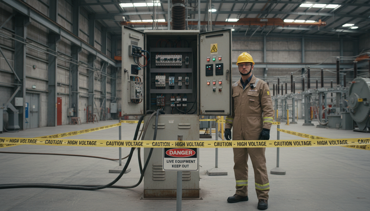
Set a clear boundary around the panel and tester. Use warning signs, barricades, or attendants where needed. Keep nonessential personnel out of the area.
Dry and stable work conditions
The panel should be stable, accessible, and free of standing water or damp surfaces. Test personnel should have secure footing and avoid awkward reach positions.
One operator in control
Assign one person to control the tester. If another technician observes or records, define roles clearly. No one should touch the panel, leads, or connected conductors while voltage is applied.
Visible indication and emergency stop
The test setup should provide clear indication when voltage is present. The operator must know how to stop the test quickly. Testers with interlocks, warning lamps, and controlled ramp functions can reduce risk when used correctly.
Discharge after testing
Capacitive circuits can hold charge after the test voltage is removed. Use the tester’s discharge function and verify discharge according to the procedure before touching conductors. Do not assume that a pass result means the circuit is safe to handle.
Lockout and energy control
Confirm that external power sources are isolated before shop testing. For field work, use approved lockout/tagout procedures and verify absence of voltage on incoming sources as required.
What a strong test procedure should include
A good hipot procedure is clear enough that two trained technicians would run the test the same way and reach the same conclusion. It does not rely on memory or tribal knowledge.
At minimum, the procedure should identify:
Procedure element | What it should define |
Equipment under test | Panel ID, rating, drawing number, revision, and serial number |
Test standard or basis | Applicable product standard, customer specification, or internal procedure |
Test points | Conductors, circuits, buses, and grounded parts included in each test |
Exclusions | Devices or circuits disconnected, shorted, bypassed, or not tested |
Test settings | Voltage type, target voltage, ramp time if used, duration, trip level, and leakage limit |
Safety controls | Boundary, personnel roles, PPE, warning signs, and discharge method |
Acceptance criteria | What counts as pass, fail, abort, or retest |
Restoration steps | Removal of jumpers, reconnection of wires, torque checks, and functional checks |
The procedure should also address what happens when a test fails. A failure process may include stopping work, discharging the unit, inspecting for visible damage, dividing the circuit into smaller sections, correcting the defect, and retesting only after approval.
Avoid repeated high-voltage testing without a reason. Dielectric tests stress insulation. Follow the applicable standard and engineering guidance for retesting after repair.
Best practices for documenting test results
Poor documentation can weaken an otherwise good test program. A sheet that says “hipot passed” may satisfy no one if a customer, inspector, or quality manager later asks what was tested and how.
Good records should allow someone to reconstruct the test without being present.
Include these details:
Panel identification, including job number, serial number, and drawing revision
Test date and location
Technician name and, if required, reviewer or witness name
Test instrument make, model, serial number, and calibration status
Applicable standard, customer specification, or internal test procedure
Circuits tested and test connection points
Components disconnected, shorted, bypassed, or excluded
Test voltage, AC or DC test type, duration, ramp settings, and trip settings
Measured leakage current or tester reading where required
Pass, fail, abort, or retest result
Corrective action for any failure
Confirmation that temporary jumpers and lifted wires were restored
Signatures or electronic approvals if required by the quality process
A simple table can make the core data easier to review.
Test item | Setting or result |
Assembly tested | Main distribution switchboard section 1 |
Test basis | Approved inspection and test plan |
Test applied | Phase conductors tied together to ground |
Sensitive devices isolated | Surge device disconnected, meter voltage inputs lifted |
Test voltage and duration | Per approved procedure |
Result | Pass |
Restoration verified | Temporary links removed and wiring rechecked |
For repeatable work, use controlled forms rather than blank notes. Digital records can help, but only if they are protected from later edits or include revision history. Attach photos only when they add value, such as showing unusual isolation steps or customer-witnessed setups.
Document failures with care. A failed dielectric test is not just a red mark. It is a clue. Record the symptoms, where the breakdown occurred if known, the corrective action, and the retest result. This information helps improve assembly practices over time.

Common mistakes that weaken the test program
Many dielectric test problems come from process gaps rather than bad equipment. Watch for these common mistakes.
Testing before the panel is truly complete
If barriers, covers, bonding jumpers, or final wiring are missing, the result may not represent the finished assembly.
Failing to control temporary changes
Lifted wires and shorting jumpers must be tracked. A forgotten jumper can cause a functional failure or equipment damage later.
Using the wrong test voltage
The correct setting comes from the applicable standard, rating, and procedure. Using a generic voltage can lead to under-testing or damaged components.
Ignoring leakage trends
A pass/fail trip is useful, but leakage readings can still tell a story. Similar panels should produce broadly similar results when tested under similar conditions. A reading that is much higher than expected deserves review, even if it passes.
Skipping discharge verification
Stored charge can remain after the tester turns off. Discharge and verification steps protect the technician who removes leads or restores wiring.
Treating documentation as paperwork
Records are part of the test. If the record does not show what happened, the test may be hard to defend.
Building safety and compliance into the workflow
The best test programs make safe, compliant testing the normal way to work. That starts before the tester is plugged in.
Panel design should support inspection and testing. Clear terminal labeling, accessible ground bars, suitable barriers, and documented isolation points all make dielectric testing safer. Engineering drawings should identify components that need special test treatment. Production teams should know which assemblies require hipot testing and which acceptance criteria apply.
Quality teams can support consistency by maintaining approved procedures, current forms, equipment calibration records, and training records. Supervisors can reduce risk by making sure technicians have time to test properly, rather than rushing final inspection at the end of a build.
For nationwide work, customer specifications and local code enforcement practices can vary. Keep the test basis clear on each project. If the equipment will be listed, labeled, inspected, or witnessed, align the test plan with those requirements before the final day of production.
A practical workflow looks like this:
Review the drawing, standard, and customer test requirements.
Inspect the completed assembly for readiness.
Identify sensitive electronics and required isolation steps.
Set up the test area and safety boundary.
Verify tester calibration and settings.
Apply the test according to the procedure.
Discharge and verify safe condition.
Restore all temporary changes.
Document results and corrective actions.
10. Complete final inspection or functional testing as required.
A better final test protects people, equipment, and reputation
Hipot testing for switchboards and control panels safety compliance and documentation best practices all point to the same principle: the test must be planned, controlled, and recorded. A dielectric withstand test is not a quick box to check at the end of assembly. It is a final safety and quality gate for completed electrical equipment.
The strongest programs combine accurate standards-based test settings, careful isolation of sensitive electronics, trained personnel, controlled work areas, and complete records. When those pieces are in place, dielectric testing does more than find faults. It builds confidence that the panel is ready for the next stage, whether that is shipment, commissioning, inspection, or long-term service.


Comments