
Earth Resistance Testers for Safer Grounding in Industry, Substations and Renewables
- 17 hours ago
- 9 min read
A grounding system is easy to ignore until it fails. When it does, the results can be severe: electric shock risk, damaged equipment, nuisance trips, fire hazards, and unstable protection systems. The ground grid, rod, plate, or electrode may be buried out of sight, but its condition directly affects site safety and electrical reliability.
That is where earth resistance testers earn their place. These instruments measure how effectively a grounding system can dissipate fault current into the soil. In industrial plants, substations, and renewable-energy sites, they help maintenance teams verify that grounding remains safe, compliant, and fit for changing conditions.

Why grounding quality matters across critical electrical sites
Grounding performs several jobs at once. It provides a low-resistance path for fault current, helps protective devices operate correctly, stabilizes voltage references, and reduces touch and step voltage hazards. It also supports lightning protection, surge protection, and electromagnetic compatibility.
Poor grounding can be caused by many factors:
Corroded rods or conductors
Loose bonding points
Dry or frozen soil
Construction damage
Undersized grounding systems
Changed site loads or added equipment
Poorly installed connections
Theft or removal of copper conductors
A visual inspection may find some of these issues, but it cannot confirm the ground system’s electrical performance. Earth resistance testing provides measurable proof. It turns a hidden underground condition into data technicians can trend, compare, and act on.
The target resistance value is not the same for every site. Requirements vary by system design, code, utility rules, equipment manufacturer guidance, and risk level. A small installation may have different acceptable limits than a high-voltage substation or large industrial plant. The key is to test against the design requirement and keep records over time.
How earth resistance testers support industrial sites
Industrial sites often have complex electrical networks. Motors, drives, transformers, generators, welders, process equipment, and control systems all depend on safe and stable grounding. A poor ground can expose workers to shock hazards and create hard-to-trace equipment faults.
In manufacturing plants, earth resistance testers help verify:
Main grounding electrodes
Building grounding grids
Machine bonding points
Generator and transformer grounds
Lightning protection systems
Hazardous-area grounding and bonding
Temporary grounding for construction or shutdown work
Grounding problems in industrial sites rarely announce themselves clearly. They may appear as intermittent control faults, communication noise, drive trips, or unexplained damage after storms. Testing helps separate grounding issues from equipment issues.
For example, a production line with repeated variable frequency drive faults may not have a drive problem at all. The issue could be poor bonding between equipment frames and the plant grounding network. An earth resistance test, combined with continuity checks and inspection, can point the team toward the real fault path.
The benefit is practical: fewer surprises, safer maintenance work, and fewer repeated equipment failures.
Their role in substations and power distribution
Substations place even higher demands on grounding systems. During a fault, large currents may flow into the ground grid. If the grid resistance is too high, dangerous touch and step voltages can develop around structures, fences, control cabinets, and operating handles.
Earth resistance testers support substation safety by helping teams assess:
Ground grid resistance
Fence bonding
Transformer and neutral grounding
Control building grounding
Surge arrester grounding
Communication system grounding
Temporary work grounds during outages
Substation testing often needs careful planning. The grounding system may be large, interconnected, and influenced by nearby buried metallic structures. Test leads may need long spacing, and the site may need to coordinate testing during low-load or planned maintenance periods.
For substations, measurement accuracy matters, but so does interpretation. A number alone is not enough. Teams need to compare test results with design calculations, previous readings, soil conditions, and changes made to the site.

Why renewable-energy installations need regular ground testing
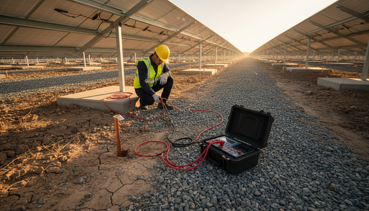
Solar farms, wind farms, battery storage systems, and hybrid renewable sites often cover large areas. Their grounding systems are spread across exposed terrain, where soil moisture, corrosion, vibration, and lightning activity can all affect performance.
In solar installations, grounding supports:
PV array frames and mounting structures
Inverter stations
Transformer pads
Combiner boxes
Fence systems
Lightning and surge protection
DC and AC equipment bonding
In wind farms, grounding is even more closely tied to lightning risk. Turbine towers, blades, nacelles, transformers, and collection systems can experience harsh electrical and environmental stress. The grounding system needs to carry fault and lightning currents safely while protecting equipment and people.
Battery energy storage systems also need reliable grounding. Power conversion equipment, containers, HVAC systems, fire detection equipment, and communication networks depend on correct bonding and grounding. A weak ground can complicate fault detection and increase the risk of equipment damage.
Renewable sites can also change quickly. New inverters, expanded arrays, added battery containers, or replacement transformers may alter grounding paths. Regular testing creates a baseline and shows whether the grounding system still performs as intended after expansion or repair.
Key features that make modern testers useful
Earth resistance testers vary from simple handheld instruments to advanced clamp and multifunction test sets. The right model depends on the site, grounding design, and testing method.
Feature | Why it matters |
Three-pole and four-pole testing | Supports fall-of-potential testing for individual electrodes and larger grounding systems |
Clamp-on testing | Allows some checks without disconnecting the ground electrode, useful where shutdowns are difficult |
Soil resistivity measurement | Helps design new grounding systems and diagnose changes in soil performance |
Noise rejection | Improves readings in electrically active environments such as substations and plants |
Data storage | Helps teams compare results across inspections and prove test history |
Rugged construction | Supports field work in dust, rain, heat, and rough terrain |
Clear display and lead checks | Reduces setup errors and speeds up repeat testing |
Safety ratings | Helps protect technicians when testing near energized electrical systems |
Clamp-on testers are especially useful for maintenance checks where the grounding system has multiple parallel paths. They can measure loop resistance without driving auxiliary stakes in some conditions. They do not replace every fall-of-potential test, but they are valuable for screening and troubleshooting.
Four-pole testing is more common when higher accuracy is needed or when lead resistance may affect the reading. Soil resistivity testing is useful before construction and when a site shows seasonal grounding changes.
The best tester is not always the most complex one. It is the one that matches the site’s grounding layout, safety requirements, and documentation needs.
Best practices for conducting earth resistance tests
Good results come from good method. A high-quality tester cannot fix poor setup, bad connections, or unsafe work planning.
Start with the site records
Before testing, review drawings, previous test reports, grounding design targets, and known equipment changes. Look for additions such as new transformers, generators, fences, solar inverters, or battery containers.
If old test results are available, compare them by location and season. A single reading is useful, but a trend is far more powerful.
Choose the right test method
Common methods include:
Fall-of-potential testing
Often used for ground rods, grids, and electrode systems. It uses auxiliary current and potential stakes placed at measured distances.
Clamp-on testing
Useful for multi-grounded systems where disconnecting the electrode is not practical.
Selective testing
Measures a specific electrode in a larger system without fully disconnecting it, when the instrument and setup support it.
Soil resistivity testing
Used for design and diagnostics. It helps determine how the soil itself affects grounding performance.
The chosen method should fit the grounding system’s size and configuration. Large substations and renewable sites may need longer lead runs and more careful spacing than small industrial electrodes.
Control the test setup
Technicians should:
Clean connection points before attaching leads
Place auxiliary stakes firmly in the soil
Keep test leads separated to reduce coupling
Check for buried utilities before driving stakes
Avoid testing during lightning activity
Record temperature, weather, and soil conditions
Repeat readings when results look unstable
Follow lockout, tagout, and electrical safety procedures
Soil condition matters. Dry soil usually has higher resistance than moist soil. Frozen ground can also raise readings. For this reason, test records should include conditions at the time of measurement.
Document results clearly
A useful report should include:
Test date and location
Instrument model and calibration status
Test method used
Electrode or grid tested
Lead spacing or clamp location
Measured resistance values
Weather and soil notes
Photos or sketches of setup
Comparison with previous readings
Recommended corrective work
Documentation helps maintenance teams defend decisions, schedule repairs, and show that grounding systems receive proper attention.

Common grounding challenges and how to solve them
Grounding systems age, and site conditions rarely stay fixed. The following issues appear often across industrial, utility, and renewable-energy settings.
Corrosion weakens buried components
Copper, galvanized steel, clamps, and connectors can corrode, especially in coastal areas, chemically active soil, or sites with stray currents. Corrosion increases resistance and can create open or weak connections.
The solution is to inspect accessible joints, use compatible materials, apply listed connectors, and replace degraded components. Where soil is aggressive, design teams may choose corrosion-resistant materials or protective measures.
Soil conditions change with seasons
A grounding system that performs well in spring may show higher resistance after a long dry period. Seasonal testing can reveal whether values remain acceptable in the worst expected conditions.
Solutions include adding ground rods, installing ground rings or grids, improving electrode depth, or using approved ground enhancement materials where suitable and permitted.
Parallel paths hide weak electrodes
Large sites often have many bonded paths. A faulty electrode may still appear acceptable because current returns through other paths. Clamp and selective testing can help isolate individual electrodes without fully dismantling the grounding network.
Teams should not rely on one convenient measurement point. Test at critical locations and compare results across the system.
Electrical noise affects readings
Substations, drives, inverters, and transmission equipment can introduce noise into test circuits. This can cause unstable or misleading readings.
A modern tester with noise rejection helps, but setup still matters. Use proper lead routing, verify connections, repeat tests, and test during suitable operating windows when needed.
Physical damage goes unnoticed
Excavation, vehicle traffic, theft, and construction work can damage grounding conductors. Renewable sites are especially exposed because long grounding runs may cross open terrain.
Routine inspection should accompany testing. Look for cut conductors, missing bonds, damaged exothermic welds, loose lugs, and exposed buried cable.
Field examples that show the impact
The following examples are generalized from common field scenarios. They show how earth resistance testing can move a team from guesswork to targeted action.
A manufacturing plant reduced unexplained equipment trips
A plant experienced repeated trips on a packaging line after summer storms. Maintenance teams replaced surge devices and checked panels, but the problem returned.
Earth resistance testing found that one section of the plant grounding system had a much higher resistance than adjacent areas. Inspection revealed a corroded bond between an equipment grounding conductor and a buried grounding loop.
After repairs and retesting, the readings returned close to the plant’s historical baseline. The line still needed normal maintenance, but the storm-related trips stopped recurring. The test did not just find a number out of range. It identified where the grounding path had weakened.
A substation found a fence bonding issue before an outage
During planned maintenance, a utility crew tested several grounding points around a distribution substation. The main grid readings were acceptable, but a fence section showed inconsistent results.
Further inspection found a failed bond across a gate hinge area. In normal conditions, the defect was easy to miss. During a fault, it could have created a touch voltage hazard.
The repair was simple compared with the potential risk. The team installed an approved bonding jumper, documented the work, and added the location to future inspection routes.
A solar farm traced inverter alarms to grounding variation
A solar facility reported intermittent inverter alarms during dry months. Electrical checks did not show a single failed inverter, and alarms appeared in one area of the site more than others.
Testing showed higher ground resistance near a section of the array built on rocky, dry soil. The site reviewed the grounding design, added supplemental electrodes where needed, and improved bonding checks during maintenance.
The result was a more stable electrical reference for equipment and a clearer maintenance baseline. Testing turned a vague reliability issue into a defined grounding problem.
Building a stronger grounding maintenance program
Earth resistance testers are most valuable when they are part of a repeatable program, not a one-time activity. A strong program includes baseline testing, planned intervals, repair thresholds, and clear records.
A practical schedule may include testing:
After installation and commissioning
After major electrical upgrades
After excavation or site construction
After lightning damage or surge events
During planned shutdowns
At regular maintenance intervals
When equipment shows signs of grounding-related faults
The exact interval should reflect site risk, code requirements, soil conditions, and operating history. High-risk locations and harsh environments often need more frequent checks.
Training also matters. Technicians should know how to select the correct method, place test stakes, recognize suspect readings, and work safely around energized equipment. Calibration should stay current, and reports should be stored where maintenance and engineering teams can use them.
A grounding system cannot be judged by appearance alone. It needs measurement, history, and maintenance. Earth resistance testers give teams the evidence they need to protect people, reduce equipment risk, and keep electrical systems working as designed. For industrial plants, substations, and renewable-energy installations, that evidence is not optional. It is a core part of electrical safety.


Comments