
Acrel Meter Commissioning CT Ratios Phase Mapping and Reading Checks
A meter can be wired neatly, powered up correctly, and still give numbers that make no sense. The usual cause is not the meter itself. It is the setup around it: the current transformer ratio, the phase allocation, the wiring mode, or the direction of the CTs.
Acrel meters are used across a wide range of electrical monitoring tasks, from simple panel metering to multi-circuit energy measurement and building monitoring. During commissioning, the aim is simple: make the displayed values match the real electrical load. That means checking the configuration before trusting readings for energy use, load balance, power factor, alarms, or reporting.
This guide explains the key settings and checks that help produce sensible readings. It also shows where ProSense Instruments can help when selecting a compatible Acrel meter and current-transformer package for a new panel or retrofit.
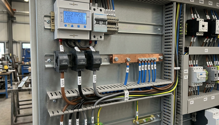
Commissioning proves the readings are believable
Commissioning is more than entering a few menu values. It confirms that the meter, CTs, voltage references, and load wiring all describe the same electrical system.
A good commissioning process answers several basic questions:
Does the meter know the correct CT primary and secondary ratio?
Is each current input paired with the correct voltage phase?
Are the CTs fitted in the correct direction?
Is the meter set for the right network type, such as single-phase, 3-phase 3-wire, or 3-phase 4-wire?
Do voltage, current, kW, kVA, kVAr, power factor, and energy values agree with independent checks?
Do import and export readings move in the expected direction?
If these items are wrong, the meter may still display stable readings. They will simply be wrong readings. A phase mismatch can make power factor look poor when the load is normal. A reversed CT can show negative kW on an importing load. An incorrect CT ratio can make the current and power readings ten times too high or too low.
For safety, all installation and live testing should be carried out by competent electrical personnel using suitable procedures and test equipment. CT secondary circuits also need careful handling, especially where traditional 5 A or 1 A secondary CTs are used.
CT ratios set the scale of the current reading
The CT ratio tells the meter how to convert the current signal it receives into the real primary current flowing in the conductor.
For example, a CT marked `250/5 A` means 250 A in the primary conductor produces 5 A in the secondary circuit at rated conditions. If the meter is set to `100/5 A` by mistake, every current and power value based on that CT will be scaled incorrectly.
The same principle applies to CTs with 1 A outputs, mA outputs, or dedicated split-core accessories designed for a specific meter input. The meter setup must match the CT type being used.
Common CT ratio details to confirm
Item to check | Why it matters |
CT primary rating | Sets the real current range, such as 100 A, 250 A, or 600 A |
CT secondary output | Must match the meter input, such as 5 A, 1 A, or a dedicated low-current signal |
CT type | Solid-core, split-core, Rogowski coil, or meter-specific accessory types may not be interchangeable |
Accuracy class | Affects how closely readings track the real current |
Burden and lead length | Long secondary wiring or the wrong burden can affect accuracy |
CT orientation | Controls whether the meter sees import or export power correctly |
Do not assume that any CT with the right physical size will suit the meter. The input type matters. A meter designed for 5 A CTs should not be connected to a low-current split-core CT unless the manufacturer supports that combination. The reverse is also true.
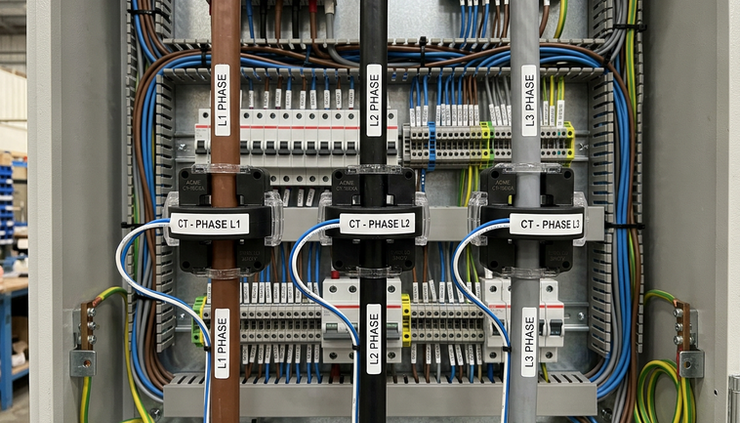
CT primary rating should suit the load
A CT should cover the expected maximum current without being so oversized that low-load readings become poor. For a circuit that normally runs at 40 A and may peak at 80 A, a much larger CT may not give the best low-current performance. For a main incomer with high load variation, the selection needs more care.
For retrofit work, the physical window size also matters. The CT must fit around the cable or busbar. Split-core CTs make retrofits easier because they can be installed without disconnecting the conductor, but they still need the right electrical rating and meter compatibility.
CT direction affects power flow
Most CTs have a direction mark, often shown as `P1` to `P2`, `K` to `L`, or an arrow. This mark indicates the intended direction of power flow. In a typical import installation, the CT orientation should match the flow from supply to load.
If a CT is reversed, the meter may show negative kW on that phase, export energy when the site is importing, or a total power value that looks too low because one phase subtracts from the others.
The fix may be physical, by turning the CT around, or logical, if the meter supports polarity correction in its settings. Physical correction is usually the clearest option because it leaves the wiring and the displayed values easier to understand later.
Phase mapping keeps voltage and current in step
Phase mapping means matching each current input to the correct voltage phase.
In a 3-phase system, the meter calculates power by comparing voltage and current waveforms. If the current from L1 is paired with the voltage from L2, the current value may still look normal, but power and power factor can become misleading.
A typical setup has:
L1 voltage reference paired with L1 CT input
L2 voltage reference paired with L2 CT input
L3 voltage reference paired with L3 CT input
Neutral connected where required by the meter and network type
The phase names on site may use L1, L2, L3, R, S, T, A, B, C, or colour-based labelling. The label style is less important than consistency. Each voltage input and CT input must refer to the same physical phase.
Signs of incorrect phase allocation
Incorrect phase mapping often shows up as values that are possible in theory but unlikely in the real installation. Watch for these signs:
One phase shows a very low or negative power factor while similar loads on other phases look normal.
Total kW is much lower than expected even though current is present on all phases.
One phase reports negative kW while the others report positive kW.
kVA looks reasonable, but kW does not match the known load.
Phase angles do not match the expected sequence.
Swapping two CT inputs makes the readings suddenly look sensible.
A motor load, heater bank, UPS input, chiller, or distribution board with known loads can help expose mapping errors. The more balanced and predictable the load, the easier it is to spot a mismatch.

The meter configuration should match the electrical system
Before taking readings seriously, gather the information needed to configure the meter. This is best done before site work starts, especially when a panel builder, electrical contractor, controls engineer, and monitoring provider are all involved.
Configuration item | Typical question to answer |
Network type | Is it single-phase, 3-phase 3-wire, or 3-phase 4-wire? |
Nominal voltage | What voltage should the meter expect at its voltage inputs? |
CT ratio | What is the primary and secondary rating of each CT? |
CT input type | Does the meter accept 5 A, 1 A, mA, Rogowski, or a dedicated CT? |
PT or VT ratio | Is a potential transformer used for medium-voltage or special systems? |
Frequency | Is the system 50 Hz or 60 Hz? |
Demand settings | What averaging period is needed for demand values? |
Energy direction | Should the meter record import only, export, or both? |
Communications | What address, baud rate, protocol, and parity settings are required? |
Alarms and setpoints | What limits should trigger outputs or alerts? |
Not every installation uses every setting. Many low-voltage installations only need the network type, CT ratio, voltage input, frequency, and communications values. Larger systems may need demand intervals, pulse outputs, data logging, or remote monitoring settings as well.
A clear commissioning sheet helps. Record the meter model, serial number, circuit name, CT ratio, CT type, phase allocation, communication address, and final test readings. This makes later fault-finding much faster.
Reading checks should compare more than amps
After configuration, the displayed readings should be checked against the real installation. Start simple, then move to calculated values.
Check voltage first
Voltage readings are usually the easiest to confirm. Compare the meter display with a suitable test instrument at the same point in the circuit. Check phase-to-neutral and phase-to-phase values as appropriate for the network.
If the voltage values are wrong, fix that before checking power readings. Incorrect voltage inputs can make every calculated value unreliable.
Check current on each phase
Use a clamp meter or another suitable reference instrument to compare each phase current. Allow for normal tolerance, load variation, and the accuracy of both instruments.
If the meter current is consistently high or low by a simple factor, suspect the CT ratio. For example, a setup error between 100 A and 1,000 A primary ratings will show as a clear scaling problem. If only one phase is wrong, check that CT and its input wiring.
Check kW and power factor together
Current alone does not confirm correct phase mapping. A meter can show the right amps and still calculate the wrong power.
Compare kW against a known load where possible. Resistive loads, such as heaters, are useful because they usually have a power factor close to unity. Motors, drives, UPS systems, and LED lighting can have lower or more complex power factor values, so they need more care when used as references.
Power factor should make sense for the load type. A lightly loaded motor may show a lower power factor. A heater should not usually show a very poor power factor. If the value looks strange, check phase mapping and CT direction before assuming the load is the cause.
Check import and export direction
On an importing load, active power should normally show as import. If the site has solar generation, battery systems, or other sources, test under a known operating condition where possible. Confirm whether the meter records import and export energy into the correct registers or display fields.
This check matters for billing support, tenant metering, energy reporting, and load studies. Direction errors can pass unnoticed if only current is checked.
Symptoms often point to the setup error
Symptom | Likely area to inspect |
All currents are scaled too high or too low | CT ratio setting |
One phase current is zero | CT wiring, CT position, or open input |
One phase shows negative kW | CT direction or current input polarity |
Total kW is much lower than expected | Reversed CT or phase mismatch |
Power factor is poor on one phase only | Phase allocation or CT polarity |
Voltage readings are correct but power is wrong | CT mapping, CT direction, or wiring mode |
Communications values do not match the display | Register mapping, scaling, or data type interpretation |
Remote monitoring can add another layer of confusion. A site display may be correct while a building management system shows the wrong value because the external system applies the wrong scale factor or reads the wrong register. Always confirm whether the issue sits in the meter setup, the wiring, or the data system.

Meter and CT selection should happen together
Selecting the meter first and choosing CTs later can create avoidable problems. The meter input type, circuit current, physical space, accuracy needs, and installation method all need to line up.
For a new installation, the preferred package might use solid-core CTs installed during panel build. For a retrofit, split-core CTs may reduce downtime. For high-current or awkward busbar installations, a different sensing method may be more practical. Where communications are needed, the meter also has to suit the monitoring system, not just the electrical panel.
ProSense Instruments can help match the Acrel meter to the right current transformers for the application. That includes checking the measurement task, circuit rating, CT ratio, installation constraints, and communication needs before equipment is supplied.
This is especially useful where the installation includes:
Multiple outgoing feeders with different current ratings
Tenant or sub-metering requirements
Retrofitted panels with limited space
Solar, battery, or generator connections
Building management system integration
Demand monitoring or load studies
Mixed single-phase and 3-phase circuits
A compatible package reduces commissioning time because the meter inputs, CT outputs, and setup values are already aligned. It also lowers the risk of nuisance fault-finding caused by mismatched parts.
A practical commissioning sequence works best
A clear order prevents wasted time. The following sequence suits many low-voltage metering jobs:
Confirm the network type and voltage connections.
Confirm the CT type, ratio, and physical orientation.
Check that each CT is fitted around the correct conductor.
Match each CT input to its voltage phase.
Enter the CT ratio and any PT or VT ratio.
Set frequency, demand, energy direction, and communication values.
Compare voltage readings with a test instrument.
Compare current readings on each phase.
Check kW, kVA, kVAr, and power factor under a known load.
10. Confirm import and export direction where relevant.
11. Record final settings and test readings.
The key is not to rely on a single value. Current readings prove scale. Power readings prove phase relationship. Energy readings prove direction over time. Communications checks prove that the wider system receives the same values the meter displays.
Acrel Meter Commissioning CT Ratios Phase Mapping and Reading Checks come down to one principle: the meter must be told exactly what it is measuring and how the installation is wired.
The takeaway
Good metering starts before the display lights up. The CT ratio sets the measurement scale. Phase mapping keeps voltage and current aligned. Reading checks prove that the displayed values match the real circuit.
If the meter, CTs, wiring mode, and monitoring requirements are selected as one package, commissioning becomes much easier. For support with selecting a compatible Acrel meter and current-transformer package, contact ProSense Instruments with the circuit details, expected load current, installation type, and any communication requirements.


Comments