
Choosing Acrel Current Sensors and Transducers for AC DC Motors Batteries and PLC Inputs
Choosing a current sensor is rarely just a matter of matching the amp rating on a datasheet. The right device must match the type of current, the size of the conductor, the control system input, the installation space, and the fault conditions that may appear during real operation.
That is especially true when selecting Acrel current sensors and transducers for motors, machinery, battery systems, pumps, and industrial equipment. A pump motor, a DC battery string, and a feeder into a PLC cabinet may all need current measurement, but they do not need the same instrument.
A good selection starts with one question: what current are you actually trying to measure?

Start with AC or DC measurement
The first split is AC versus DC. It sounds basic, but it prevents many wrong purchases.
Traditional AC current transformers work by magnetic induction. They are well suited to sinusoidal AC loads such as utility feeders, pump motors, fans, compressors, and distribution circuits. They usually do not measure DC current because DC does not create the changing magnetic field needed for transformer action.
For AC machinery, an Acrel current transformer or AC current transducer may be the right fit when the signal needs to represent load current, phase imbalance, motor running status, or an overload trend. This is common in:
Pump motor monitoring
HVAC fan systems
Industrial conveyor drives
Machine tool feeders
Three-phase distribution panels
Compressor and chiller circuits
DC measurement needs a different approach. Battery banks, DC motors, solar DC strings, rectifier outputs, UPS systems, and EV-related equipment can carry steady current in one direction, or bidirectional current during charge and discharge. For these systems, Hall-effect sensing is often the better choice.
Hall-effect sensors measure the magnetic field around a conductor. Because they do not rely only on changing current, they can measure DC current, and many designs can also measure AC. Acrel Hall-effect current sensors, such as open-loop or closed-loop Hall types, are commonly used where both isolation and DC measurement are required.
When AC-only devices make sense
Use an AC current transformer or AC transducer when the circuit is AC and the output only needs to represent RMS current or load status. This can keep the installation simple and cost-effective.
A motor current input to a PLC is a common example. If the PLC only needs to know whether a motor is running, lightly loaded, or drawing too much current, an AC transducer with a 4–20 mA or voltage output can be easier to use than a raw CT.
When Hall-effect sensing makes sense
Use a Hall-effect sensor when the circuit includes DC, bidirectional current, or distorted waveforms that a standard CT cannot handle well.
This applies to:
Battery charge and discharge current
DC motor armature current
Rectifier and inverter DC links
UPS battery strings
Industrial battery systems
Equipment with mixed AC and DC sections
For battery systems, the ability to detect current direction can matter. Charging current and discharging current may need separate interpretation in a controller. In those cases, select a sensor and output format that supports the required polarity or bidirectional signal.
Match the current range to real operating conditions
The marked full-scale current on the sensor should fit the normal load, not just the maximum cable rating.
For a motor, the running current may sit well below the short-term starting current. A pump motor can draw a high inrush current when it starts, then settle into a much lower operating current. If the transducer range is too low, the output may saturate during starting. If the range is too high, the PLC may see only a small signal during normal running, which reduces useful resolution.
A practical selection process looks at three current values:
Current value | Why it matters |
Normal operating current | Sets the useful measurement range for control and monitoring |
Short-term overload or starting current | Prevents nuisance saturation or false alarms |
Fault or maximum expected current | Helps choose a safe device and installation method |
For pump systems, current can also indicate mechanical behavior. A pump that runs dry may draw less current than expected. A blocked impeller may draw more. A current transducer feeding a PLC can support these checks, as long as the selected range gives enough detail around the normal operating zone.
For machinery, think beyond the nameplate. Duty cycle, acceleration, braking, tool load, jams, and material changes can all affect current. Select a range that captures the operating pattern the control system needs to see.
A useful rule is to place normal current in the middle portion of the sensor output range where possible. That gives the PLC room to see both rising and falling current.

Check conductor size, busbar shape, and installation space
Current rating is only part of the fit. The conductor must physically pass through the sensor window.
Small control panels may use round conductors. Larger industrial systems may use thick cables, parallel conductors, or copper busbars. Battery systems may use flat bars with high DC current. Before selecting the sensor, confirm:
The outside diameter of the cable
The size and orientation of the busbar
Whether multiple conductors pass through the sensor
Bend radius and cable movement
Clearance around terminals and covers
Whether the circuit can be disconnected during installation
A closed-core sensor often performs well, but it requires the conductor to be passed through the opening. That means disconnecting the cable or installing the sensor during panel build.
A split-core sensor can open and clamp around an existing conductor. This helps with retrofit work on motors, pumps, and industrial equipment where shutdown time is limited. The trade-off is that installation must be neat. The core should close fully, and the conductor should sit correctly in the window.
For three-phase AC systems, each phase normally needs its own sensing path if phase current matters. Do not pass all three phase conductors through one current sensor unless the goal is residual current or imbalance detection with a device designed for that purpose. Passing supply and return conductors together can cancel the magnetic field and produce little or no useful current reading.
For DC battery cables, conductor placement is just as important. Keep the measured conductor centered where the sensor design expects it. Watch nearby high-current conductors, as strong magnetic fields can affect measurement if the layout is poor.
Decide what signal the controller needs
Acrel current transducers can be selected with outputs that suit different receiving devices. The right output depends on what reads the signal.
Raw current transformers often provide a secondary current, such as a low AC current proportional to the primary current. These CT outputs may go to a meter, protection relay, or power monitoring device designed for CT inputs.
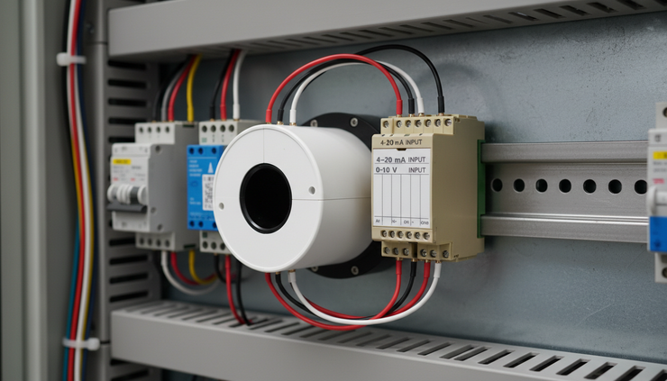
A PLC analogue input usually needs a standard process signal instead. Common choices include:
4–20 mA current output
0–5 V voltage output
0–10 V voltage output
Other low-voltage analogue ranges, depending on the device
A 4–20 mA signal is common in industrial environments because it resists electrical noise better over longer cable runs. The live zero at 4 mA also helps detect broken wiring in many systems, since an open circuit often reads near 0 mA rather than a valid minimum process value.
Voltage outputs can work well over short distances inside a control panel. A 0–10 V signal is simple to read and common on many PLC input cards. Keep cable length, noise, grounding, and input impedance in mind.
The PLC analogue input type must match the chosen transducer output. A 4–20 mA output needs a current input or an approved input resistor arrangement. A voltage output needs the correct voltage input range. The scaling inside the PLC should match the current range of the sensor.
For example, a transducer rated for 0 to 200 A with a 4–20 mA output should be scaled so 4 mA represents 0 A and 20 mA represents 200 A, unless the device is configured differently. Bidirectional DC sensors may use a signal where the midpoint represents zero current, such as a voltage centered around a reference level. In that case, PLC scaling must account for direction.
Use isolated outputs where safety and signal quality matter
Isolation separates the measured power circuit from the signal circuit. In current sensing, this can protect the PLC input and reduce problems caused by ground potential differences, noise, and high-energy conductors.
Many Hall-effect current sensors and current transducers provide galvanic isolation between the primary conductor and the secondary output. This is one reason they are often used in industrial control panels, DC systems, and machinery.
Isolation is not a substitute for proper circuit protection, insulation, spacing, or safe installation practice. It does help create a cleaner boundary between a high-current circuit and a low-voltage control system.
Look for isolated outputs when measuring:
High-current motor feeders
Battery banks and DC bus circuits
Circuits with high electrical noise
Equipment controlled by VFDs
Long cable runs between sensor and PLC
Systems where the PLC and power circuit may have different ground references
VFD-driven motors deserve extra care. The waveform may include harmonics and switching noise. A simple AC CT may work for broad load monitoring on the supply side, but current measurement on the drive output can be less straightforward. Choose a sensor type and installation point that match the purpose of the measurement. If the goal is control feedback, use equipment rated for that environment.
Apply the selection to common industrial equipment
The same selection logic changes slightly by application.
Motors and pumps
For standard AC motors on fixed-speed starters, an AC current transducer can provide a clean signal to the PLC. Select the current range around the running current, with enough headroom for starting and overload.
For pumps, current can support dry-run detection, blocked pump detection, and load trend monitoring. The signal does not replace motor protection, but it gives the control system useful process information.
For VFD-driven pumps, measure at the point that makes sense. Supply-side current may be easier to measure and cleaner for general load monitoring. Drive-output measurement needs more care because of waveform shape and switching effects.
Machinery and production equipment
Machinery often has changing loads. Cutting, pressing, mixing, crushing, and conveying can all create current patterns that show machine condition. A transducer feeding a PLC can help detect jams, overloads, underloads, and abnormal cycles.
Choose a fast enough response for the event you need to catch. Slow output filtering may hide short spikes. Very fast response may create noisy PLC values. The right balance depends on whether the signal drives control action, alarms, or trend data.
Battery and DC systems
Battery systems need DC-capable measurement. Hall-effect sensors are often the practical choice because they provide isolation and allow non-contact current measurement through a cable or busbar.
For battery applications, confirm whether current flows in one direction or both directions. A charging and discharging battery may need bidirectional measurement. The receiving PLC or battery controller must understand the output meaning.
Also check the conductor size carefully. Battery cables and busbars can be large, stiff, and difficult to reroute. A split-core or appropriately sized Hall sensor can simplify installation, but only if it fits physically and meets the measurement requirement.
Industrial feeders and equipment panels
For general feeder monitoring, the main choice is between a CT connected to a meter or a transducer connected directly to a PLC. If the PLC only has standard analogue inputs, a transducer with a 4–20 mA or voltage output is usually easier to integrate than a raw CT.
For panels with many loads, consistent output types make commissioning easier. Using the same signal standard across motors, pumps, and machinery reduces input card variety and simplifies PLC scaling.
Build a practical selection checklist
A clean selection process reduces rework. Before choosing an Acrel sensor or transducer, collect the electrical and control details.
Use this checklist:
Current type AC, DC, or bidirectional DC
Current range Normal load, starting current, overload current, and expected maximum
Conductor format Round cable, multiple cables, copper busbar, or existing installation
Installation method Split-core for retrofit, closed-core for new builds where conductors can be routed through the sensor
Output signal Raw CT output, 4–20 mA, 0–5 V, 0–10 V, or another analogue signal
PLC input type Current input, voltage input, input resolution, and scaling range
Isolation needs High-current circuits, noisy environments, DC bus systems, or different ground references
Environment Panel temperature, vibration, electrical noise, spacing, and maintenance access
Purpose of measurement Display, alarm, PLC control, load trend, energy data, or equipment protection support
This last point matters. A sensor used for a simple motor running signal can be selected differently from one used for battery charge monitoring or closed-loop machine control.

The best choice is the one that matches the whole signal chain
Current measurement starts at the conductor, but it does not end there. The sensor, output signal, cable route, PLC analogue input, and scaling must work as one chain.
For AC motors and pumps, an AC current transducer with a standard analogue output may be the simplest path into a PLC. For DC motors, battery systems, and bidirectional circuits, Hall-effect measurement is usually the right starting point. For retrofit machinery, split-core construction can save time. For high-noise or high-current equipment, isolated outputs help keep the control signal usable.
Select the instrument by the application, not by the amp rating alone. When the current type, conductor size, output signal, and PLC input all match, the measurement becomes easier to trust and easier to use.


Comments